How to Test a Vehicle Speed Sensor
If the engine stalls whilst idling, you will likely need to check several sensors (MAF, TPS, IAC, CKP) to identify the culprit. We have previously covered methods for testing:
- the crankshaft position sensor;
- the throttle position sensor;
- the idle air control valve;
- the mass air flow sensor.
Now, checking the vehicle speed sensor (VSS) yourself is added to this list.
When faulty, this sensor transmits erroneous data, which disrupts the operation of not only the engine but also other vehicle components. The Vehicle Speed Sensor sends signals to the ECU (Electronic Control Unit), which regulates engine operation at idle speed and controls the airflow bypassing the throttle valve via the IAC. The higher the vehicle speed, the higher the frequency of these signals.
Vehicle Speed Sensor Working Principle
The speed sensor mechanism in most modern cars is based on the Hall effect. During operation, it transmits frequency-pulse signals to the vehicle's ECU. For every kilometre travelled, the sensor transmits a specific number of pulses (approx. 6000 signals for many standard systems). The pulse transmission frequency is directly proportional to the vehicle's speed. The ECU calculates the vehicle's speed based on the frequency of these signals.
The speed sensor itself is located on the gearbox, within the speedometer drive mechanism. The exact location may vary between different car makes.
How to Tell if the Speed Sensor is Faulty
You should immediately pay attention to signs of failure such as:
- unstable idling;
- speedometer working incorrectly or not at all;
- increased fuel consumption;
- reduced engine power/traction.
Additionally, the on-board computer may display an error regarding the absence of a signal from the VSS (if an OBC is installed).

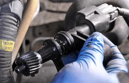
Vehicle Speed Sensor

Speed Sensor Location
Most often, the fault is caused by an open circuit, so you must diagnose the wiring first. Disconnect the power plug and inspect the contacts for oxidation and dirt. If oxidation is present, clean the contacts and use a contact cleaner spray.
Frequently, wires break near the connector, as this is where they bend, causing the insulation to wear through. You also need to check the resistance in the earth (ground) circuit, which should be approximately 1 Ohm. If the wiring is intact, you should check the sensor itself.
Many cars are equipped with a Hall effect sensor (which has three pins: earth, power, signal). However, other types of sensors exist: reed switch (tongue) and inductive sensors. First, we will look at testing the most popular type—the Hall effect VSS.
Testing the Speed Sensor (Hall Effect)
First, ensure that 12V power is reaching the plug and that there is a good earth connection.
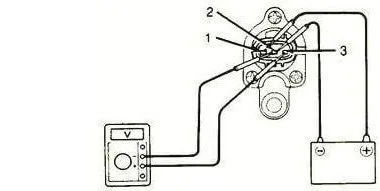
Method 1 (Testing with a Voltmeter)
- Remove the speed sensor.
- Connect the positive probe of the voltmeter to the terminal that outputs the pulse signals. Connect the second probe (negative) to the sensor body or the negative terminal of the power source. Apply 12V power to the corresponding contacts.
- Rotate the sensor axis and check if there are signals. For convenience, you can place a piece of tubing onto the axis (rotate at a speed equivalent to 3-5 km/h). The faster the rotation, the higher the voltage and frequency readings on the multimeter.
Method 2 (Without Removing from the Vehicle)
- Jack up the car so that one drive wheel is off the ground.
- Connect the voltmeter to the sensor's signal wire (you can pierce the insulation with a needle or back-probe the connector).
- Spin the wheel by hand and watch the meter. If the voltage changes (pulses appear), the sensor is working.
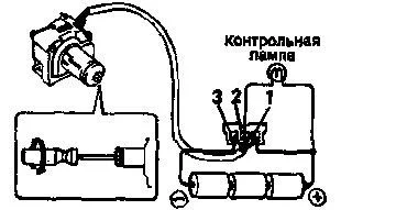
Method 3 (Testing with a Test Light)
- Disconnect the pulse wire from the sensor (or connect to it in parallel).
- Use a test light to find the positive and negative feeds (with the ignition switched on).
- Raise one wheel, as in the previous method.
- Connect the test light: one end to the battery positive, the other to the 'Signal' contact. Spin the wheel. If the sensor is functioning, the test light will flicker (the signal switches to earth).
Connection Diagram
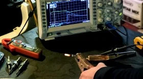
Testing VSS with a Tester
Testing the Speed Sensor Drive
- Jack up the car to raise a front wheel.
- Feel for the sensor drive protruding from the gearbox with your fingers (with the sensor itself removed).
- Ask an assistant to slowly rotate the wheel.

Speed Sensor Drive

Checking the VSS Drive
When the wheel rotates, you should feel the drive mechanism turning with your fingers. If the wheel is spinning but the drive remains stationary, the problem lies inside the gearbox (usually the teeth on the plastic drive gear have sheared off).
Testing a Reed Switch Sensor
This sensor works on the reed switch principle (closing and opening a circuit). Testing is straightforward:
- Remove the sensor or connect to its connector.
- Set the multimeter to continuity mode (or resistance measurement).
- Connect the probes to the sensor contacts.
- Rotate the sensor shaft. The meter should alternate between showing a short circuit (0 Ohms, beep) and an open circuit (infinity). If the resistance does not change or stays constantly at zero/infinity, the sensor is faulty.
Testing an Inductive Sensor
The signal from this sensor resembles a sine wave; it generates alternating current (AC) during rotation. The diagnostic principle is similar to testing a Crankshaft Position Sensor (CKP):
- Resistance Check. In ohmmeter mode, measure the winding resistance. Normal values depend on the model (usually between 500 Ohms and 2 kOhms). An open circuit or resistance that is too low indicates a failure.
- Voltage Check. Switch the multimeter to AC voltage measurement mode (AC, 200 mV or 2V limit). Spin the wheel or sensor axis. The meter should show a small voltage that increases as the rotation speed increases.
Was this article useful?
Your feedback helps us improve our content.
Related Materials


Discussion (0)
No comments yet!