Audi A6 C5 Complete Front Suspension Replacement
This photo report shows in detail how the complete front suspension replacement is carried out on the Audi A6 C5.
What parts and tools are needed to replace the front suspension on an Audi A6 C5
To perform the replacement, we will need the following tools:
- a jack,
- an inspection pit, ramp, or vehicle lift,
- penetrating oil,
- quality 16mm and 18mm sockets,
- an offset ring spanner (16/18mm) is highly desirable, as it will significantly facilitate the work,
- a hammer.
At one stage of the repair, you will need a steering joint puller with wide jaws, as well as spring compressors; it is better not to skimp on cheap ones.
And after the wishbones and shock absorbers have been replaced, it is time to go for wheel alignment.
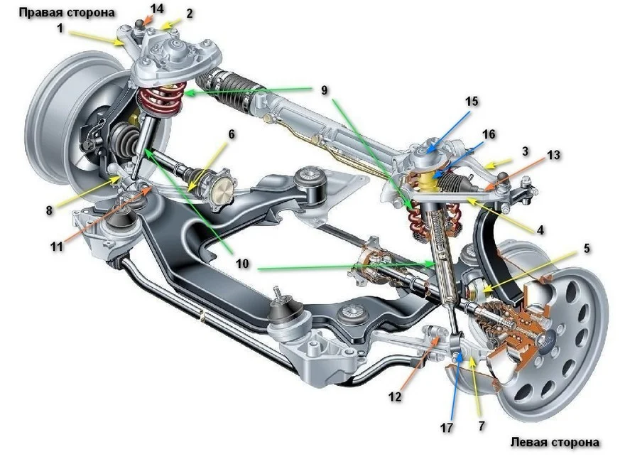
The diagram shows the parts required for replacement:
| No. on diagram | Part Name | Part Number |
|---|---|---|
| 1 | Upper front wishbone, right side | VAG 8E0 407 506 A |
| Stellox 54-00717-SX | ||
| Lemforder 13720-02 | ||
| 2 | Upper rear wishbone, right side | VAG 8E0 407 510 A |
| LYNXauto C5347R | ||
| Lemforder 21029-01 | ||
| 3 | Upper rear wishbone, left side | VAG 8E0 407 509 A |
| LYNXauto C5347L | ||
| Lemforder 21030-01 | ||
| 4 | Upper front wishbone, left side | VAG 8E0 407 505 A |
| LYNXauto C5033L | ||
| Lemforder 21615 01 | ||
| 5 | Lower rear wishbone, left | VAG 8E0 407 693 K |
| LYNXauto C5035L | ||
| Lemforder 13676 02 | ||
| 6 | Lower rear wishbone, right | VAG 8E0 407 694 E |
| LYNXauto C5035R | ||
| Lemforder 13677 02 | ||
| 7 & 8 | Lower front wishbone, both sides | VAG 4D0 407 151 H |
| LYNXauto C5034LR | ||
| Lemforder 13673 | ||
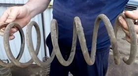
| 9 | Coil spring | VAG 8D0 411 105 DS |
| KAYABA RH 3385 | ||
| LESJOFORS LS4004256 | ||
| 10 | Gas shock absorber, both sides | VAG 4B0412031CA |
| Fenox A21008 | ||
| Stellox 4213-0060-SX | ||
| 11 | Stabiliser link, right | VAG 8D0 411 318 D |
| Mapco 49684HPS | ||
| Lemforder 21555 01 | ||
| 12 | Stabiliser link, left | VAG 8D0 411 317 D |
| Mapco 49683HPS | ||
| Lemforder 21554 01 | ||
| 13 & 14 | Track rod end, joint on both sides | VAG 4F0 498 811 |
| LYNXauto C4134LR | ||
| NK 5034756 | ||
| 15 | Shock absorber mount, left and right | VAG 4D0 412 377 F |
| Lemforder 17662 01 | ||
| Stellox 71-11180-SX | ||
| 16 | Shock absorber buffer (bump stop, damper) | VAG 8D0412131H |
| Monroe PK 088 kit (boot, bump stop) | ||
| KAYABA 915708 kit (boot, bump stop) | ||
| 17 | Front stabiliser bush | VAG 4D0 411 327 H |
| Lemforder 22304 01 | ||
| Febi 10023 |
It is recommended to use original parts manufactured by VAG or high-quality aftermarket alternatives for the replacement.
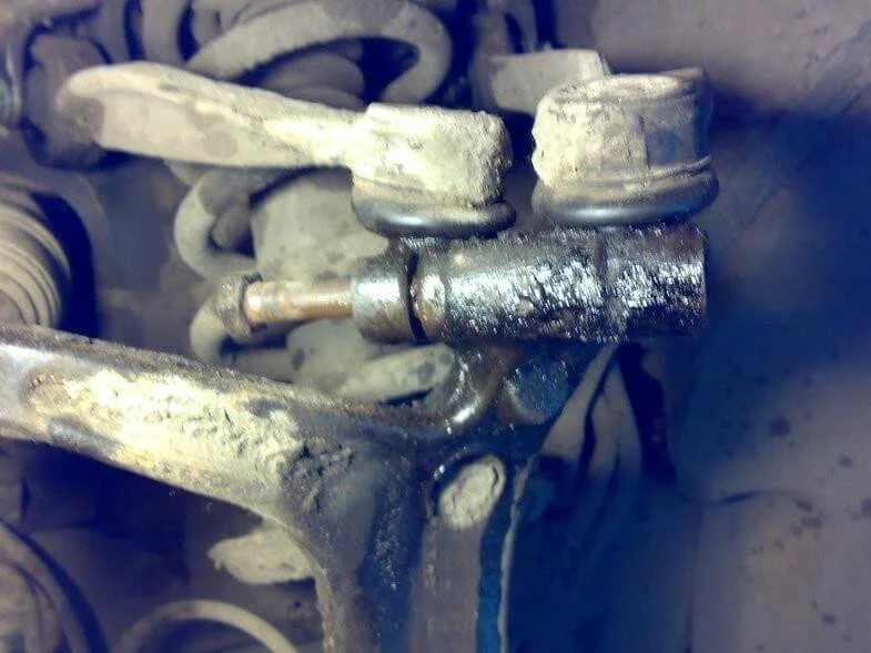
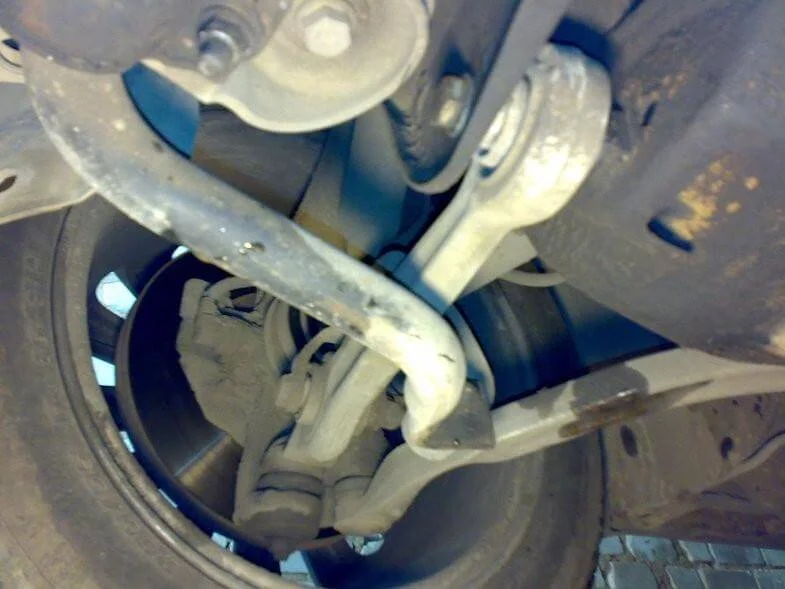
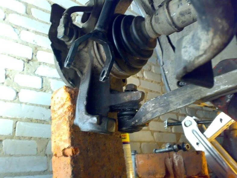
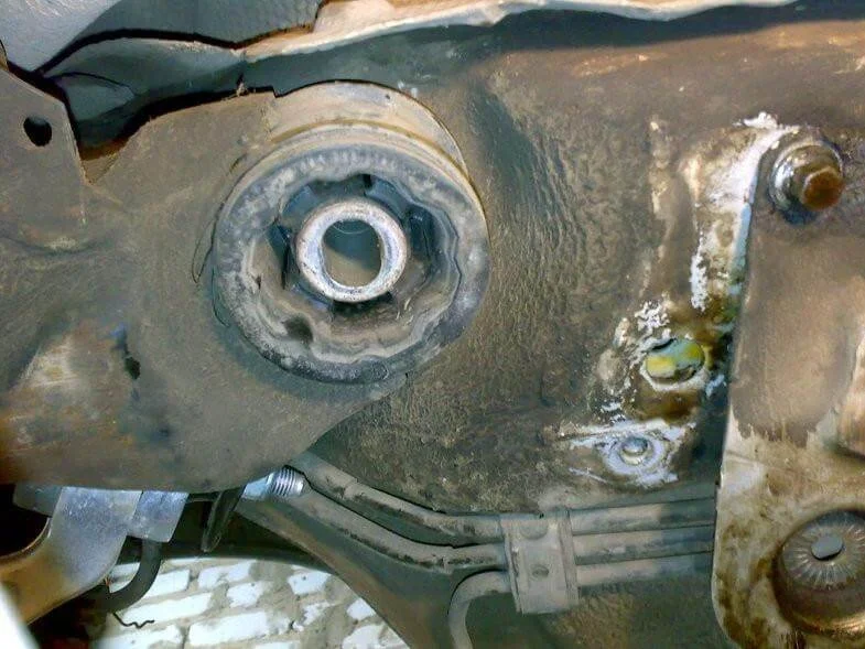
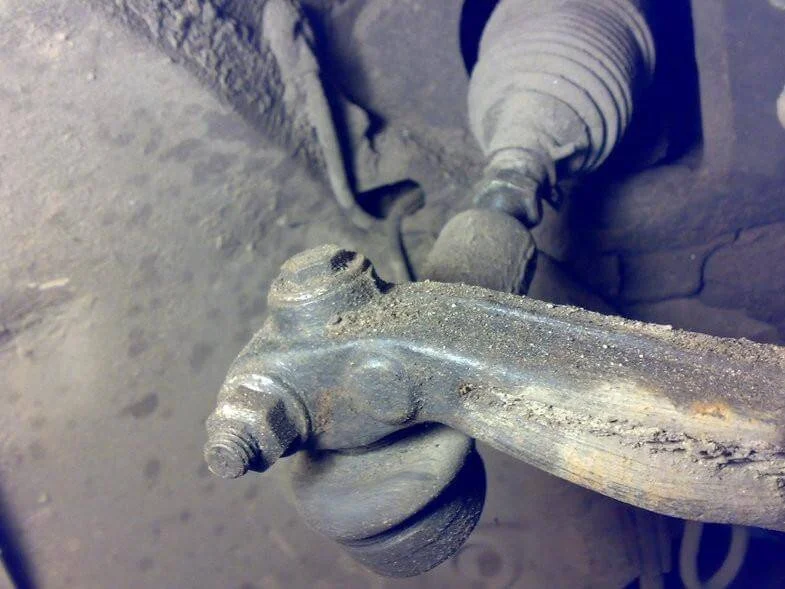
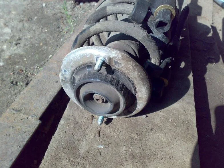
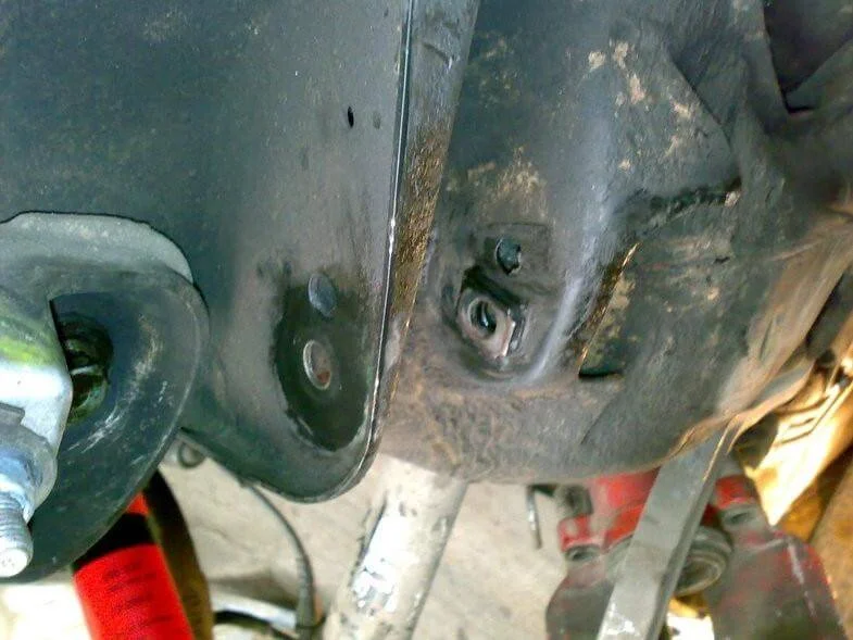
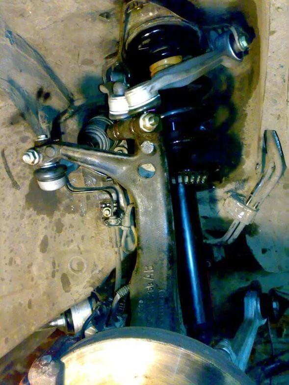
Loosen the front wheel bolts. Jack up the car and place it on a secure axle stand. Remove the wheel. Using a wire brush, clean all bolts and nuts from dirt. Pay special attention to the slots on the upper part of the steering knuckle where the upper wishbones are attached. Note the cleaned slot (left) and the uncleaned one (right). If you observe a similar situation, they must be thoroughly cleaned and soaked with penetrating oil.
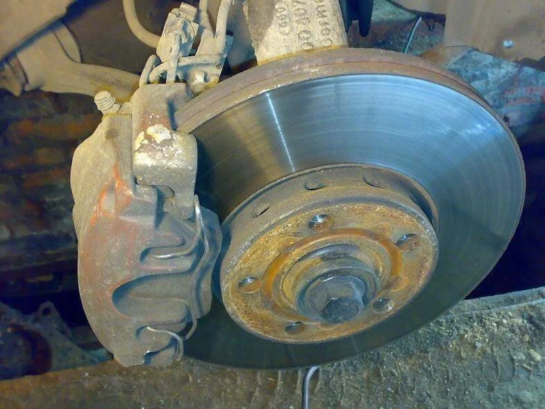
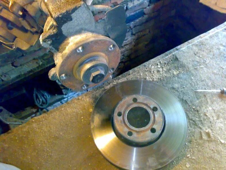
There is no single method for replacing the suspension – whether to start from the top or bottom is up to you. One way is to unscrew the 2 bolts securing the caliper carrier, then remove the brake caliper (with the carrier) and the brake disc. Suspend the caliper from the body using wire. Never leave the caliper hanging by the brake hose!
Using the necessary sockets and spanners, loosen all nuts and bolts of the front suspension! A very important point: before unscrewing, gently tap all nuts and bolts with a hammer.
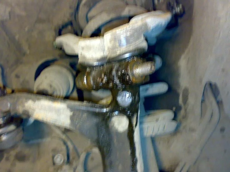
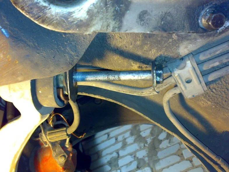
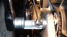
Unscrew the nut securing the upper wishbone pinch bolt. Rotate the bolt (now without the nut, using a spanner). Then gently tap it out with a hammer.
If the bolt is seized and won't move, there are many ways to remove it. For example, heat the steering knuckle and tap it out while simultaneously turning the bolt by the head (so don't rush to use brute force immediately; think through the sequence of actions carefully).
But do not rush to remove the bolt completely yet (it is enough to ensure it is moving out).
Unscrew the shock absorber bolt. Unscrew the bolts and nuts attaching the stabiliser links (drop links) to the front lower wishbone.
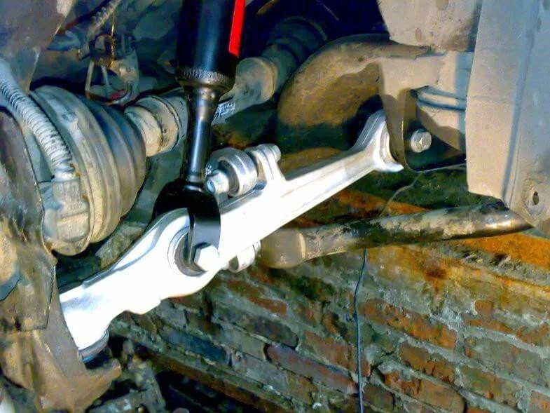
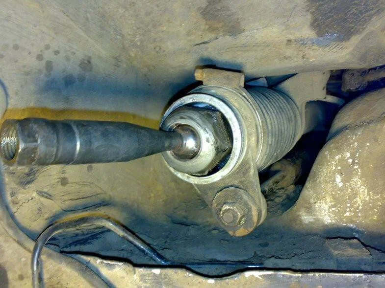
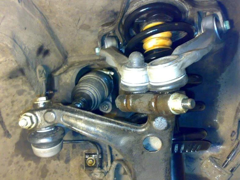
Then it is necessary to loosen the lower wishbones. To do this, unscrew the nuts of both wishbones, but not completely—leave them flush with the edge of the bolt. Install the puller. The pin of the lower wishbones has a diameter of about 20-25 mm. That is, the "jaws" of the puller must be wide.
The upper wishbone bolt is now ready for removal, as are the lower wishbones. Unscrew the upper wishbone bolt and gently tap it out of the knuckle with a hammer. Support the steering knuckle if you haven't removed the CV joint.
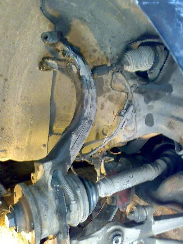
Remove the lower wishbones. To unscrew the rear lower wishbones from the body, you will need to lower the subframe slightly.
Since subframe bolts were included with the suspension kit (incidentally, the old bolt turned out to be slightly bent), the subframe bolt was completely removed, and the wishbone bolt was unscrewed with a spanner as much as possible (the bolt hits the brake lines).
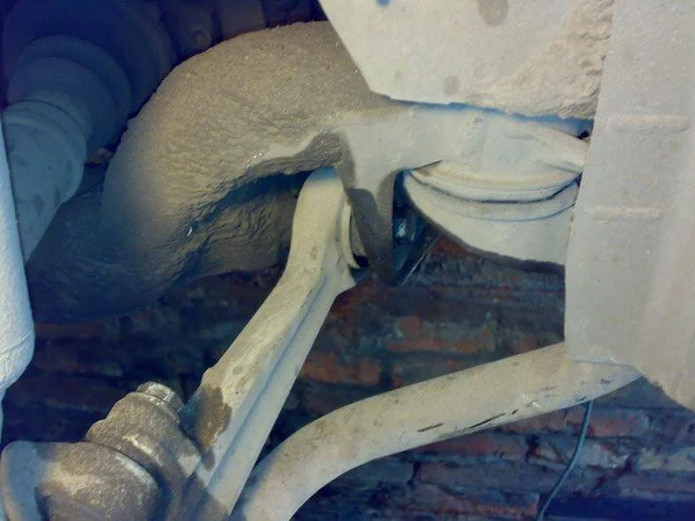
At the same time, the condition of the subframe bushes was inspected.
Next, by grabbing the bolt and pulling it down, as well as twisting the wishbone in the necessary direction, remove the old bolt. Then, take the new bolt and screw it into the subframe fully without tightening. In this way, all subframe bolts will be replaced (one by one).
To avoid lowering the subframe in the future, install the bolts the other way around—with the nut facing back, not forward. There is no fundamental difference, other than significantly making future work easier.
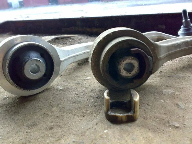
Comparison of wishbones — Original VAG vs Lemförder.
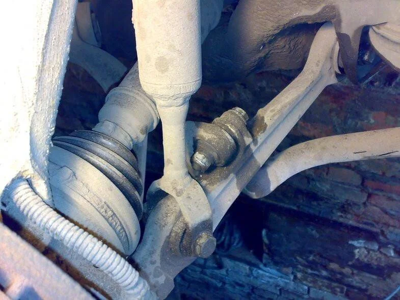
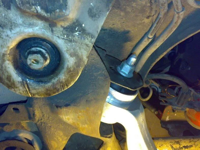
Remove the track rod end.
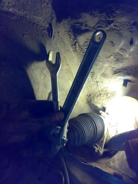
To do this, first unscrew the top bolt, then the front nut, and tap out the pin. Next, having loosened the locknut (but remembering its position), unscrew the track rod end by hand. After this, the upper wishbones are disconnected from the steering knuckle. The lower wishbones and stabiliser links are removed. The track rod end is removed. The steering knuckle is supported on a stand.
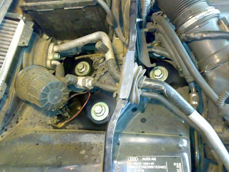
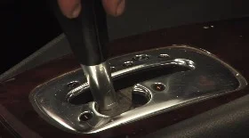
Then move on to removing the strut: unscrew the 3 bolts from under the bonnet and remove the strut.
Next stage: disassembling the strut. Unscrew the 2 nuts and remove the top mount assembly from the suspension strut.
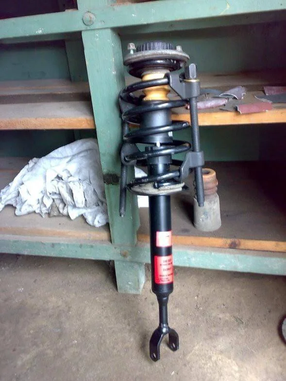
Here you will need high-quality (!) spring compressors. Compress the spring, grabbing as many coils as possible, because even 1 uncompressed coil can spring out with great force. The tension there is immense! Next, use a special 18mm socket to unscrew the shock absorber nut while holding the shock absorber shaft from turning with a hex key. An offset ring spanner won't fit there; place a socket over it. Insert the hex key through the socket and, holding the hex key, use pipe grips to turn the socket and undo the nut. Remove the top mounts, spring, dust boot, and bump stop.
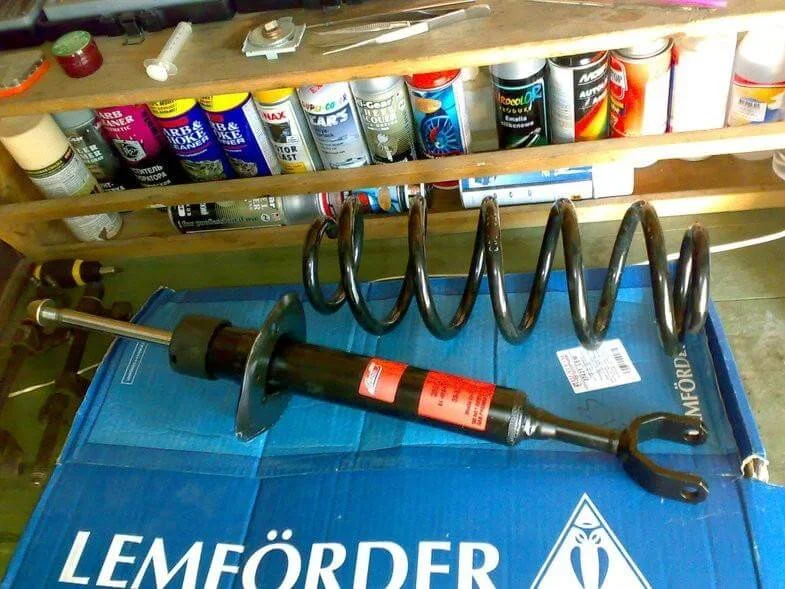
Check the condition of the lower spring pads (rubbers). Basically, that is the entire disassembly process. Assembly starts with the shock absorber strut.
Do not forget to prime the shock absorber! Install the lower bump stop onto the shock absorber cup. Install the compressed spring. On top, in reverse order, install the cup with the dust boot and bump stop fitted. Install the top mount and tighten the nut.
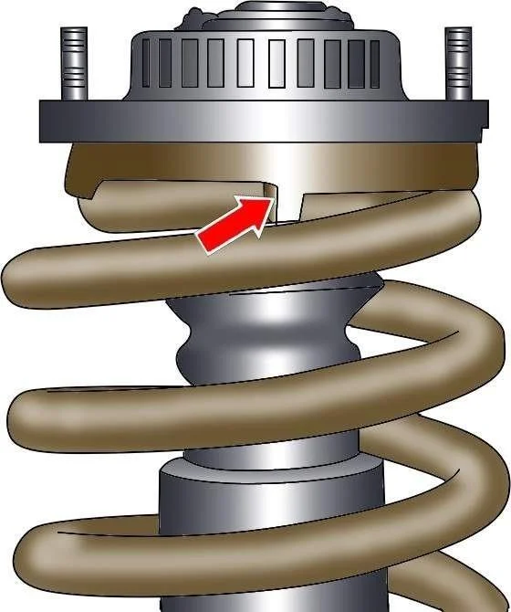
Make sure that the ends of the spring coils do not come away from the limit stops. The coil orientation diagram is shown in the image above.

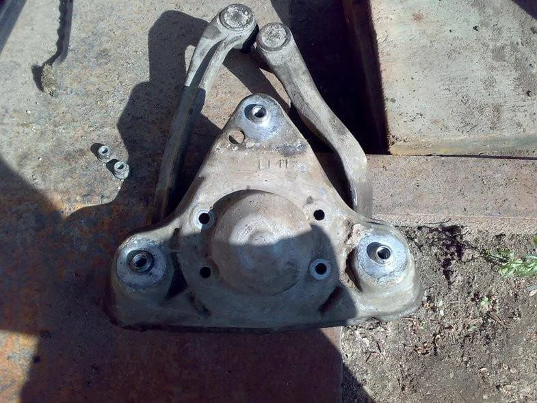
Then comes the assembly of the upper mounting plate. Remove the old wishbones. By analogy, install the new ones, observing the installation angle.
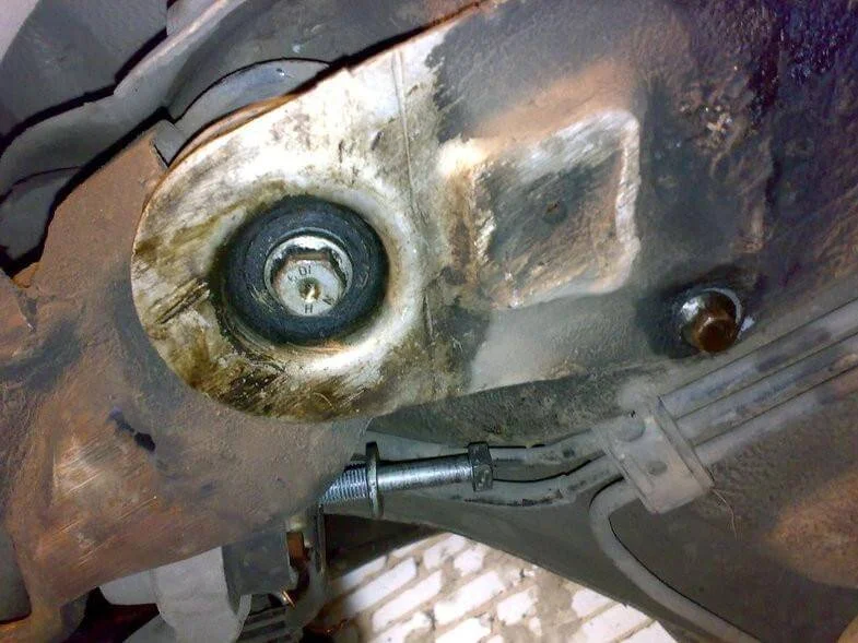
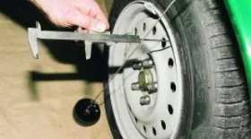
It is necessary to maintain a distance of 57 mm with a tolerance of +- 2 mm from the forward-protruding edge of the mounting plate to the wishbone. Install the top mounting plate onto the shock absorber and secure with 2 nuts with a torque of 20 Nm. Install the strut into the wheel arch niche and secure with 3 bolts (without tightening yet). Install the lower wishbones. Attach the wishbones to the steering knuckle (do not tighten yet).
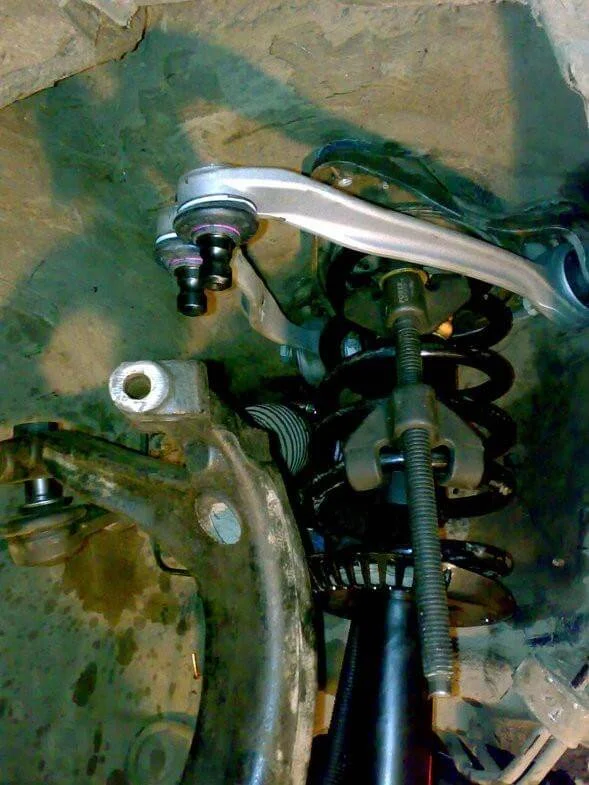
Fit the upper wishbones to the steering knuckle, bending them down by hand.
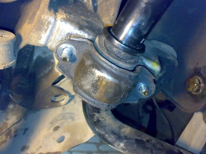
Additionally, the stabiliser bushes were replaced – unscrew 2 nuts, lower the stabiliser, and change the rubber bush, having previously degreased the surface. Condition: applying grease or oil is forbidden. Tighten 2 new nuts.
Install the drop links (stabiliser links), not forgetting their correct orientation. Attach the suspension strut to the lower wishbone. Install the track rod ends. To do this: take the old track rod end and place it against a wall. Place the new one next to it. Mark the position of the nut (transfer from old to new). Remove the nut from the old one and thread it onto the new one to the same distance – the point is not to upset the wheel alignment angles too much and to drive to the tracking centre without major issues. Additionally, you can remove the boots from the rack and grease the ball joints with synthetic grease. The steering will become somewhat lighter. Plus, tighten the 38mm nut (securing the pin itself).
Screw the new track rod end into the tie rod. Tighten the lock nut. Install the track rod end into the steering knuckle. Fix it with the large bolt. Only after that, screw in the top (small) bolt.
Tighten the 3 bolts of the upper shock absorber mount – torque 75 Nm. It remains to tighten the wishbones. Remember: wherever there are silent blocks (bushes)—namely the shock absorber attachment to the lower wishbone, the lower wishbone attachment to the body, and the stabiliser link—all this is tightened only when standing on wheels (under load)! Tighten the other ball joints with the hub jacked up, although it is not critical. Don't forget the wheel alignment/tracking.
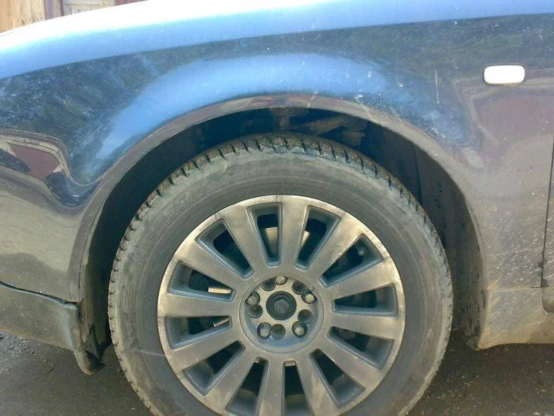
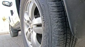
Car stance BEFORE.
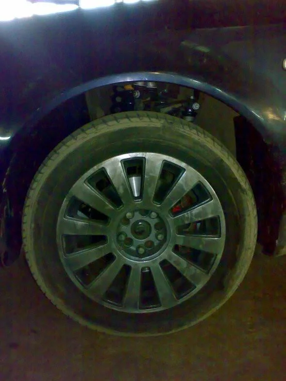
Car stance AFTER.
Was this guide useful?
Your feedback helps us improve our content.
Related Materials

Discussion (0)
No comments yet!