Checking the Alternator Voltage Regulator

Checking the alternator voltage regulator is necessary when battery problems arise: it either undercharges or overcharges. When such symptoms appear, it is time to inspect this unit.
A functioning regulator should cut off voltage in the range of 14.4–14.5 V
The device's task is to regulate the voltage of the current supplied from the alternator to the battery. If the regulator fails, the battery either does not charge enough or the electrolyte boils due to overcharging, which critically reduces the battery's lifespan.
The prospect of destroying a battery because of a small component is not appealing, so it is important to monitor the condition of the regulator (often referred to as the "brush pack" or "regulator module"). To test it correctly, you need to determine the type of device.

Types of Voltage Regulators
Understanding the device type will determine the testing procedure. Regulators are of two types:
- integrated;
- separate (external).
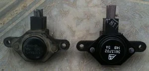
In the first case, the regulator housing is combined with the brush assembly and is located directly on the alternator. In the second case, it is a separate unit on the vehicle body within the engine bay.
A feature of modern regulators is a non-separable housing sealed with compound. It makes no sense to repair them due to their low cost, so diagnostics are reduced to identifying the fault and replacing the unit entirely.
Symptoms of a Fault
With low voltage, the battery does not charge. You won't be able to start the car in the morning, and while driving, you will notice dim headlights and malfunctions in electrical appliances.
With high voltage, the electrolyte boils away. A white deposit appears on the battery casing, and headlight bulbs burn out frequently.
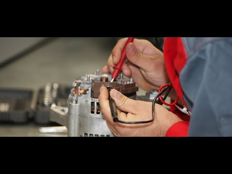
Symptoms, faults, alternator and voltage regulator repair
Additional symptoms:
- the warning light does not illuminate on the dashboard when the ignition is switched on;
- the battery indicator does not go out after starting the engine;
- headlight brightness depends on engine RPM (if the light is dim at idle but brightens when revving the engine, the problem is often in the regulator);
- the car has stopped starting normally;
- constant rapid battery discharge occurs;
- vehicle dynamics drop, especially at high RPM.
Causes of Regulator Failure
The main reasons for failure:
- short circuit (including inter-turn short circuit in the field winding);
- breakdown of the rectifier bridge diodes;
- reverse polarity when connecting the battery;
- moisture or oil ingress into the alternator;
- brush wear;
- mechanical damage or manufacturing defects.
The Simplest Testing Method (Without Removal)
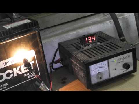
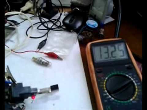
A quick method is to measure the voltage at the battery terminals with a multimeter. It does not guarantee 100% that the regulator is at fault (the diode bridge or the alternator itself may be defective), but it allows you to quickly assess the state of the system.
Algorithm:
- Start the engine and warm it up to operating temperature.
- Connect the multimeter to the battery terminals (observing polarity).
- At idle (without load), the voltage should be in the range of 13.5–14.4 V.
- Switch on the load (headlights, heater, screen demister). The voltage may drop slightly, but not below 13.0–13.2 V.
- Increase the RPM to 2000–2500 rpm. The voltage should be around 13.8–14.5 V.
If the voltage is below 13 V, there is no charging. If it is above 14.8 V, there is overcharging (the regulator is not cutting off the current). In both cases, a detailed check is required.
Testing an Integrated Regulator
Testing the voltage regulator (e.g., Lada 110)
For accurate diagnostics, the regulator must be removed. You will need: an adjustable power supply unit (PSU), a 12V bulb (3–5 W), and wires.
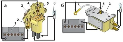
Testing the voltage regulator (model 37.3701): 1 — Battery (or PSU); 2 — earth; 3 — regulator; 4, 5 — brush terminals; 6 — test lamp.
The essence of the method:
- Connect the bulb to the brushes (regulator outputs).
- Apply power ("positive" and "negative") from the PSU to the corresponding regulator inputs.
- Set the voltage to 12–13 V. The bulb should light up.
- Gradually increase the voltage. When the threshold of 14.2–14.5 V is reached (depending on the model), the bulb should go out.
- When the voltage is lowered back, it should light up again.
If the lamp does not light up initially or does not go out when the voltage rises above 15 V, the regulator is faulty.
Testing the Voltage Regulator on Older Vehicles (e.g., Lada Classic)
Testing the voltage regulator on Lada Samara vehicles
Different types of alternators are found on "classic" models. Older designs (like the G-221) used an external relay. Since 1996, generators such as the G-222 and 37.3701 have used built-in integrated modules. The algorithm for testing them is identical to that described above: the lamp should go out when the operating voltage is exceeded.
Testing a Separate Regulator
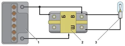
Diagram for an external regulator (G-222): 1 — Battery; 2 — regulator; 3 — lamp.
External regulators mounted on the bodywork are checked similarly. "Positive" is applied to the input (usually terminal 15 or B), "Negative" to the housing, and the lamp is connected in place of the field winding (terminal 67 or DF).
At 12 V, the lamp lights up; at 14.5 V, it goes out. Any other behaviour indicates a breakdown.
Testing Relay Type 591.3702-01
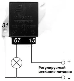
Testing circuit for relay type 591.3702-01
This relay was fitted to rear-wheel drive VAZ cars. It has two main contacts: "67" (to the alternator) and "15" (from the ignition switch). The housing serves as the earth.
Testing scheme:
- PSU "Minus" — to the relay housing.
- PSU "Plus" — to terminal "15".
- Bulb — between terminal "67" and the housing (earth).
The principle is the same: the cut-off should occur around 14.2–14.5 V.
For reference, data for the classic electromechanical RR-380 (Lada 2101):
| Voltage parameters (at 50°C): | |
|---|---|
| Stage I | no more than 0.7 V drop |
| Stage II (regulated) | 14.2 ± 0.3 V |
| Armature-core gap | 1.4 ± 0.07 mm |
Testing a Three-Level Regulator

Adjustable power supply
Three-level regulators allow manual voltage switching (e.g., min. 13.6 V, normal 14.2 V, max. 14.7 V). When testing, switch the mode toggle and ensure the bulb goes out at the voltage corresponding to the selected mode.
Dangerous Alternator Testing Method
Among old-school drivers, there is a common tip to check the alternator by removing the battery terminal while the engine is running. Supposedly, if the engine doesn't stall, the alternator is working.
The battery acts as a buffer, smoothing out voltage ripples. Disconnecting it causes a sudden voltage spike (Load Dump), which can instantly burn out electronics: from the voltage regulator and radio to the engine control unit (ECU). This method was only suitable for vintage cars without electronics.
Recommendations for Increasing Service Life
To ensure the regulator and alternator last longer:
- keep the unit clean, as dirt impairs heat dissipation;
- check the alternator belt tension;
- monitor the condition of contacts and wiring (oxidation creates excess resistance);
- periodically measure the voltage at the battery terminals.
Summary
Checking the voltage regulator yourself is within the capability of any driver. The main thing is to remove the part and assemble a simple circuit with a bulb. If tests show a fault, the regulator should be replaced, as modern semiconductor elements are usually not repairable.
Was this article useful?
Your feedback helps us improve our content.
Related Materials


Discussion (0)
No comments yet!