How to Test an Ignition Coil
The ignition coil is designed to create the high voltage required by the spark plug to generate a spark. Its correct operation is essential for the engine to function properly. Essentially, the coil is a transformer: 12 V is supplied to the primary winding from the battery, and a voltage of several thousand volts is output. The causes of failure are typical: inter-turn short circuits, broken wires, or damage to the insulation or housing. Let's look at the signs of malfunction and diagnostic methods.
Ignition Coil Operating Principle
An ignition coil is a step-up transformer. Structurally, it consists of two windings: primary (low voltage) and secondary (high voltage).
In a simple standard coil, the primary winding has 100...150 turns of thick copper wire. The secondary winding consists of 30,000...50,000 turns of thin wire. The 'negative' of the secondary winding is often connected to the 'negative' of the primary, while the 'positive' goes to the high-voltage terminal.
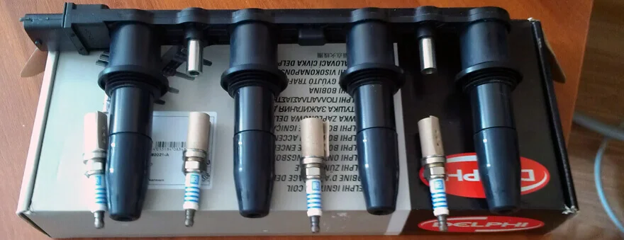
In individual coils (Coil-on-Plug or COP), which are mounted directly onto the spark plug, the design is more complex. They often incorporate a diode to cut off self-induction currents, and high voltage is supplied directly to the plug via a spring contact.
Double-ended coils (waste spark systems) supply a spark simultaneously to two cylinders (one spark is the working spark, the other is a 'waste' spark on the exhaust stroke).
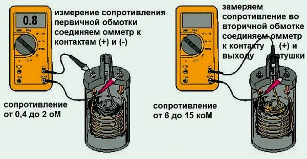
The main parameter for basic diagnostics is the electrical resistance of the windings. For a working coil, the primary winding resistance is usually 0.5...3.5 Ohms, and the secondary is between 6 and 15 kOhms (values depend on the specific car model). If multimeter measurements show significant deviations, the unit is faulty.
Symptoms of Failure
Characteristic symptoms of ignition system problems:
- the engine misfires (runs roughly), and the problem worsens over time;
- interruptions (misfires) on a cold engine or in damp weather;
- hesitation or a drop in revs when pressing the accelerator pedal sharply;
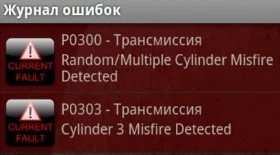
- activation of the Check Engine light (error codes P0363 or P0300-P0304).
These signs can also indicate faulty spark plugs, so diagnostics usually begin with checking the plugs before moving on to the coils.
Causes of Faults
- Natural wear and overheating. Winding insulation ages and dries out over time, leading to inter-turn short circuits.
- Moisture and dirt. Water or road salts entering the unit cause contact corrosion and surface breakdown of the insulation.
- Vibration. This is particularly relevant for individual coils that are rigidly mounted on the engine.
- Bad spark plugs. An increased gap in the spark plugs overloads the coil, forcing it to work at its limit, which quickly causes it to fail.
How to Test an Ignition Coil
We will consider three testing methods: from simple visual checks to instrumental analysis.
1. The 'Spark Test' Method
The simplest way to identify a completely dead coil.
- Disconnect the high-voltage lead or coil from the spark plug in the cylinder.
- Insert a known good spark plug into the tip/boot.
- Press the metal part of the spark plug housing (the thread) against the engine 'earth' (an unpainted metal part).
- Ask an assistant to crank the engine with the starter.
- Observe the spark: it should be powerful and bright violet/blue. A dim yellow spark or no spark indicates a fault.
If you have individual coils (COP), it is easier to test them by swapping them: switch the coil from the misfiring cylinder with a coil from a working one. If the problem moves to the other cylinder, the coil is faulty.
2. Testing with a Homemade Spark Gap Tester (Syringe Method)
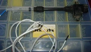
Testing with a spark plug in open air is not always reliable: it is easier for the coil to bridge the gap at atmospheric pressure than inside the cylinder under compression. To simulate the load, a spark gap tester is used.
A simple DIY tester can be made from a medical syringe: cut off the nozzle and insert two wires inside to simulate electrodes. Make the distance between them adjustable.
The principle is as follows: if you widen the electrodes in the syringe to 10–15 mm, the spark should still bridge this gap. This is equivalent to bridging a normal gap (1 mm) under pressure in the cylinder. If there is a spark at a small gap, but it disappears or becomes thin and weak when the distance is increased, the coil is 'half-dead' (has an inter-turn short) and will not work under load.
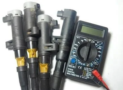
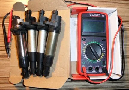
3. Measuring Winding Resistance
The most accurate method for home conditions is checking with a multimeter. You need to measure the resistance of the primary and secondary windings and compare them with the factory specifications.
Procedure:
- Switch the multimeter to resistance measurement mode (Ohms).
- Measure the primary winding. Usually, these are the '+' and '-' contacts (or the control terminal). Normal range: 0.5...3.5 Ohms.
- Measure the secondary winding (high voltage). Place one probe on the high-voltage output and the second on the earth (or the second high-voltage output for double-ended coils). Normal range: 6...15 kOhms.
Interpreting results:
- Resistance below normal: A short circuit (inter-turn) has occurred in the coil. It will overheat and produce a weak spark.
- Infinite resistance (open circuit): The wire inside the coil is broken; there will be no spark at all.
If you are checking individual coils with 3–4 contacts (with a built-in transistor/ignition module), it is difficult to check the primary circuit with a standard multimeter — you need the exact pinout to avoid burning out the built-in electronics. In such cases, it is better to use the coil swap method.
Oscilloscope Diagnostics
The most professional method. An oscillogram shows the coil's operation in dynamics. Characteristic 'decaying oscillations' at the end of the spark burn indicate that the unit is healthy. If there are no oscillations or the graph has an incorrect shape, there is an inter-turn short circuit. This method allows you to find a fault even if it only appears intermittently.
Was this article useful?
Your feedback helps us improve our content.
Related Materials


Discussion (0)
No comments yet!