How to check a crankshaft sensor?
The Crankshaft Position Sensor (CKP) is designed to synchronise the ignition system and fuel injector operation in a petrol injection engine. A fault here means the ignition timing will be advanced, retarded, or lost completely. This causes unstable running, power loss, or a failure to start the engine.
There are three types of sensors: inductive (magnetic), Hall effect, and optical. The first two are the most common. Below, we examine common faults and diagnostic methods.
Symptoms of a crankshaft sensor fault
Regardless of the CKP type, the symptoms of failure are similar. If the crankshaft sensor is faulty, the following signs will indicate it:
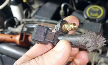
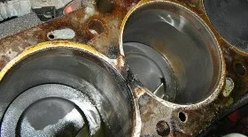
Sensor failure is often caused by a buildup of metal swarf
- impossible to start the engine (starter motor turns, but no ignition);
- engine cuts out while driving or coming to a stop;
- rough or fluctuating idle speed;
- power loss, hesitation during acceleration;
- pinking (knocking) occurs under load.
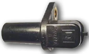
Sensor design and types
To perform a proper check, you need to understand exactly which sensor is fitted to your vehicle.
Main varieties:
- Inductive sensor. Consists of a magnetised core and a coil. It generates a voltage pulse when the pulley teeth pass by. Does not require external power, usually has 2 pins.
- Hall sensor. Works on the Hall effect principle and contains an integrated circuit board. Requires a power supply, usually has 3 pins (power, earth, signal).
Three ways to test the crankshaft sensor
Before starting any instrument checks, always inspect the sensor visually. Often the cause is simply dirt or metal swarf on the sensor tip, or damage to the wiring near the connector.
1. Checking with an OBD-2 scanner
The quickest way to localise the problem without dismantling anything. You will need a standard diagnostic adapter (e.g., ELM327) and a smartphone.
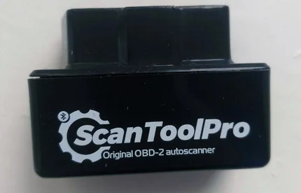
Diagnostic scanner plugs into the OBD2 port
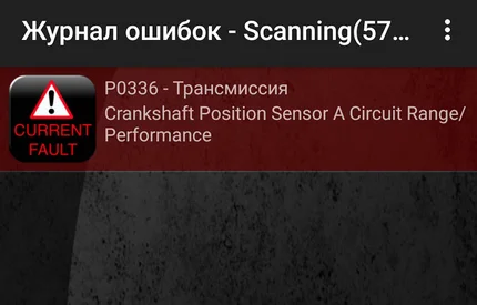
Fault code in the diagnostic app
Connect the scanner to the OBD2 port and read the errors via an app (Car Scanner, Torque, etc.). The main CKP fault codes are:
- P0335 — Crankshaft Position Sensor A Circuit Malfunction (No signal).
- P0336 — Crankshaft Position Sensor A Circuit Range/Performance.
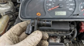
2. Checking with a multimeter (for inductive sensors)

Example of checking a CKP sensor
This method is suitable for inductive sensors (with two pins). You will need a multimeter set to resistance mode (ohmmeter).
Procedure:
- Unplug the connector from the sensor.
- Touch the multimeter probes to the sensor terminals.
- Normal winding resistance is usually between 500...900 Ohms (check your vehicle manual for exact figures).
If resistance is infinite, there is an open circuit in the winding. If it is too low, there is an internal short circuit. In both cases, the part must be replaced.
3. Checking inductance and wiring
If your multimeter measures inductance, you can check this parameter as well. The normal range is usually 200...400 mH.
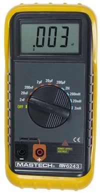
Inductance meter
However, it is far more important to check the integrity of the wiring and connector, as the problem is often not the sensor itself, but a lack of contact.
To test (with connector removed and ignition on):
- For Hall sensors (3 pins): Use a multimeter in voltmeter mode to check if power is arriving (usually 5V or 12V) and if there is a good earth connection.
- For inductive sensors (2 pins): Perform a continuity test on the wires from the sensor connector to the ECU.
Using a megohmmeter with high voltage (500V) to check insulation on a car is not recommended, as you risk damaging the electronic control unit (ECU).
4. Checking with an oscilloscope
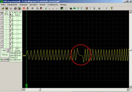
Waveform of a healthy sensor. The missing teeth gap is clearly visible.
This is the most accurate method, allowing you to visualise the signal waveform. It is suitable for both inductive and Hall sensors.
- Connect the oscilloscope probes to the sensor signal wire (without disconnecting the sensor from the system, using back-probing needles).
- Start the engine or crank it with the starter.
- A clear waveform should appear on the screen.
For an inductive sensor, this will be a sine wave with amplitude increasing with RPM. For a Hall sensor, look for square wave pulses. Crucially, the graph should be free of noise or dropouts and clearly show the gap for the missing teeth on the pulley.
Summary
The crankshaft position sensor is a critical component. Start your diagnosis by checking with a scanner and inspecting the wiring. If you have an inductive sensor, measure its resistance. In difficult cases, an accurate diagnosis can only be made using an oscilloscope or by swapping the sensor for a known good unit.
Was this article useful?
Your feedback helps us improve our content.
Related Materials


Discussion (0)
No comments yet!