Replacing the clutch and differential bearing on Volkswagen Vento / Golf Mk3
This photo guide demonstrates how to replace the clutch and eliminate differential play in the gearbox on Volkswagen Vento and Golf Mk3 cars.
The main reason for the repair was oil leaking through the differential seals and its presence in the engine bay. Simply replacing the seals made no sense, as the differential had significant axial play (around 10 mm). It was decided to remove the gearbox, replace the worn differential bearing, and install a new clutch kit at the same time.
Parts and Tools
To perform the work, you will need:
- an inspection pit or ramp;
- two jacks and sturdy axle stands;
- a set of spanners and sockets (including 12-point sockets);
- a torque wrench;
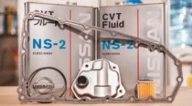
- a clutch kit and differential bearing.
Part numbers are provided as an example for the Golf Mk3 (1.8 L, 90 hp, ABS, ADZ engines).
| Item | Part Number |
|---|---|
| Clutch pressure plate (cover), Ø 215 mm | VAG 028 141 025 B |
| Luk 122 011 5 10 | |
| SACHS 3082 194 233 | |
| Clutch disc (friction plate), outer Ø 215 mm | VAG 028141034N |
| Jp Group 1130201600 | |
| Luk 322 0147 11 | |
| Release bearing | VAG 02A 141 165 M |
| Luk 500 0440 10 | |
| SKF VKC 2241 |
For 1.8 and 2.0 engines with the 020 type gearbox, part numbers and clutch disc diameters (ranging from 210 mm to 228 mm) may vary, so parts must be selected strictly according to the VIN code.
Below is the repair process for the 5-speed gearbox type 020 (code CHE). The removal and installation procedure is similar for the type 085 gearbox (fitted to 1.4 and 1.6 L engines).
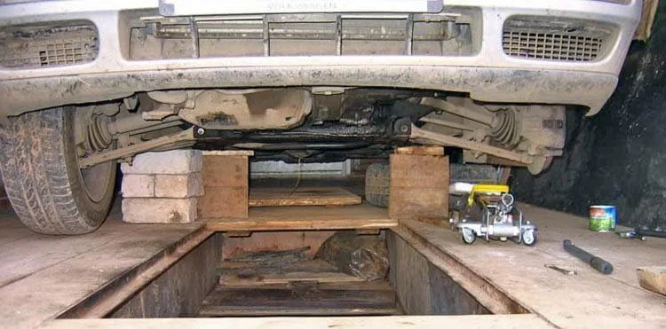
Drive the vehicle onto the inspection pit and secure it firmly on axle stands.
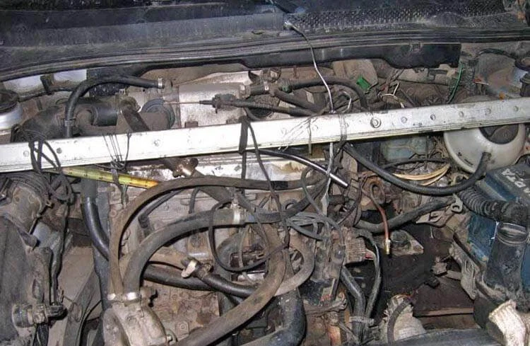
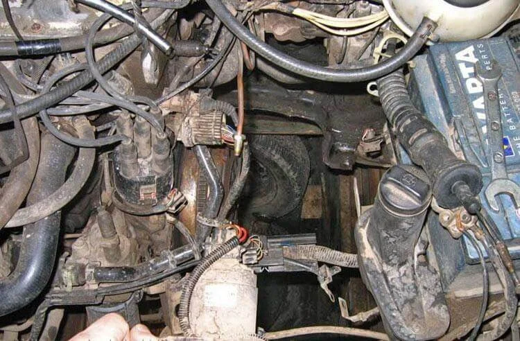
Since you will need to unbolt two of the three engine mounts to remove the gearbox, the power unit must be supported. You can use a proper engine support beam or, as shown here, a sturdy improvised structure made of metal angles resting on the wings via wooden blocks. The engine is suspended using a steel cable (3 mm).
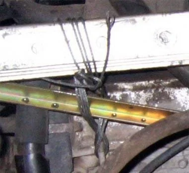
Cable attachment point on the engine from one side.
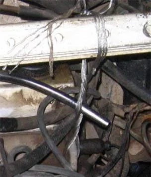
Attachment point on the other side.
Now you can undo the fixings:
- Front mount bolts (16 mm socket): one bolt connecting the mount to the rubber cushion, and three bolts connecting the mount, starter, gearbox, and engine.
- Rear mount bolts. Three bolts attaching to the gearbox and the cushion bolt.
- Inner CV joint bolts connecting to the gearbox flanges (6 bolts per CV joint).
- Gear selector linkages, speed sensor and reverse light connectors, clutch cable.
The gearbox remains attached to the engine by three bolts (two at the top, one at the bottom). Once these are removed, carefully slide the gearbox off the guides and lower it. The unit weighs approximately 30 kg.
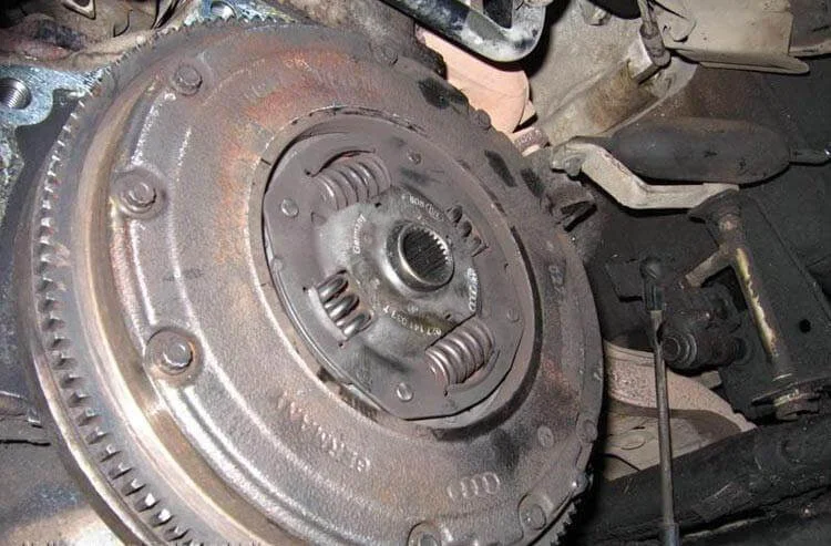
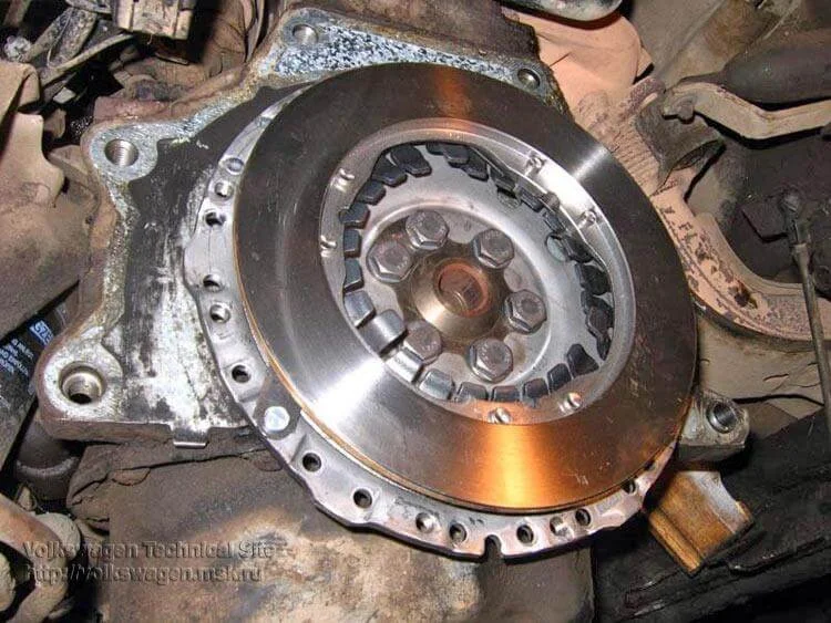
After removing the gearbox, the flywheel and clutch are accessible.
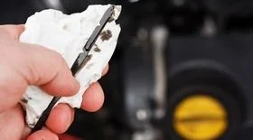
Visual inspection of the old clutch disc.
Undo the 9 bolts securing the flywheel to the pressure plate (requires a 9 mm 12-point socket) and remove the flywheel.
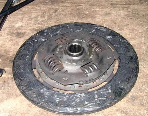
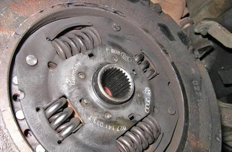
Remove the old clutch friction plate.
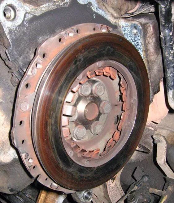
Inspect the pressure plate (clutch cover).
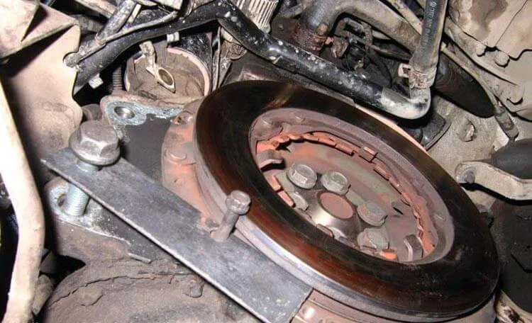
Undo the bolts securing the pressure plate to the crankshaft and remove it.
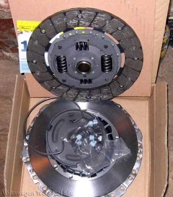
Prepare the new clutch kit (Luk is used in this case).
Bolt on the new pressure plate (new bolts are usually included). Install the pressure plate, friction disc, and flywheel. Start the bolts but do not fully tighten them yet, so the clutch disc can still move. Important: the disc must be perfectly centred. It is best to use a clutch alignment tool (dummy input shaft), but if unavailable, you can use a vernier calliper to measure equal distances from the edges. Once centred, tighten the flywheel to the torque specified in the manual.
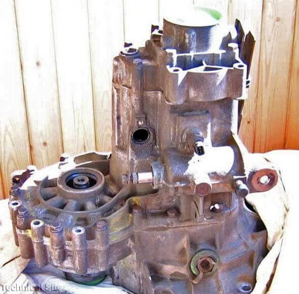
Proceeding to the gearbox repair (type 020, CHE). To access the differential, the gearbox casing must be split. The full shaft disassembly process is omitted here.
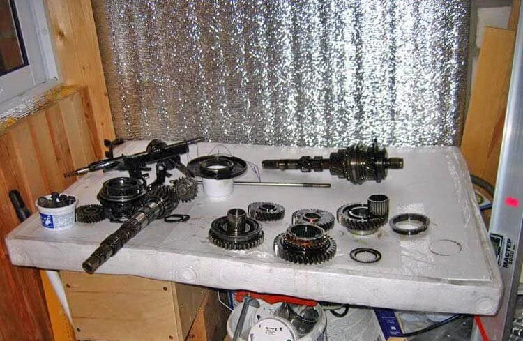
Internal view of the gearbox with the casing cover removed.
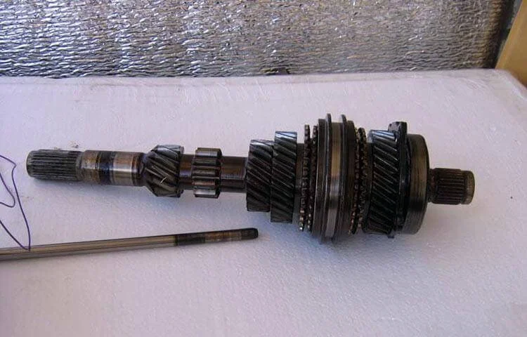
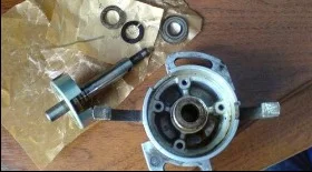
Gearbox input shaft.
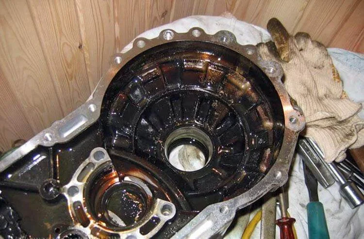
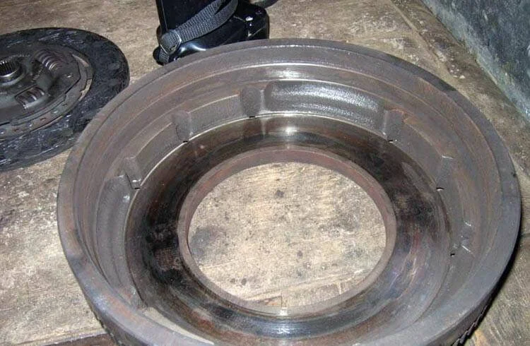
Gearbox housing (clutch bell housing).
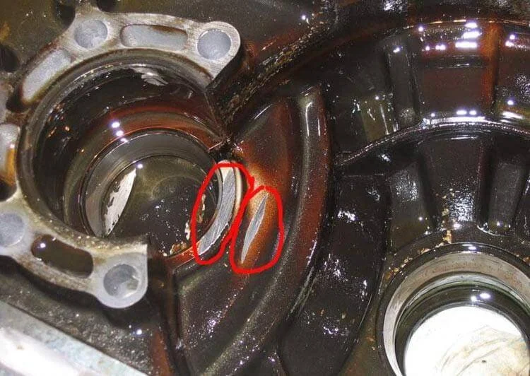
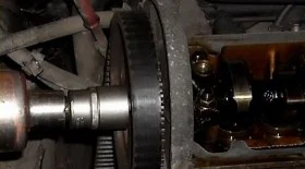
The photo shows signs of wear ('grooves') on the gearbox housing caused by the excessive play of the loose differential.
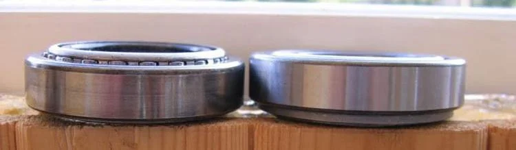
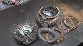
The play was caused by the tapered roller bearing, which was heavily worn and had settled.
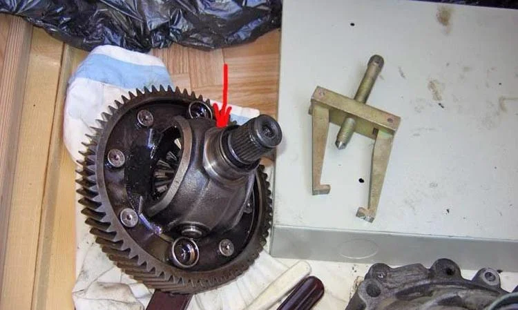
Install the new bearing (SKF used here).
Warning: according to factory specifications, replacing tapered differential bearings compulsorily requires selecting a shim to ensure correct preload. In this example, the old shims were retained, but this is a risky approach. To guarantee the unit's longevity, you must measure the play with a dial gauge and select the correct shim thickness. Reassemble the gearbox using sealant for the housing mating surfaces.
Was this guide useful?
Your feedback helps us improve our content.
Related Materials
Discussion (0)
No comments yet!