Audi 100 Steering Rack Rebuild
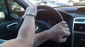
A leak developed on the Audi 100 steering rack. This is one of the signs of unit failure, so a repair kit was purchased, and a refurbishment was carried out: disassembly, inspection, rebuild, and reassembly.
To repair the rack yourself, you will need:
- a repair kit (e.g., 443498020A);
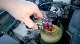
- 2 litres of PAS fluid (G002 or an equivalent, e.g., Febi 6162);
- a new rubber steering rack gaiter.
Tools:
- 6mm Allen key;
- sockets with extensions;
- a drift/punch;
- 10mm and 13mm spanners;
- a hammer;
- petrol (for cleaning);
- cleaning cloths.
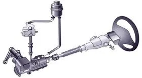
Removing the rack from the car is not difficult, but carrying out a full repair (stripping, cleaning, replacing seals, and assembling) is much more complex. This photo report will help you understand the nuances of the process.
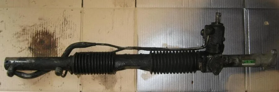
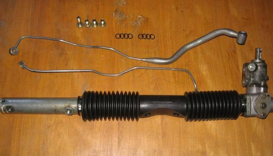
Remove the rack from the car. If there is a leak, it usually looks very dirty. If possible, it is best to clean it with a pressure washer and detergent before disassembly.
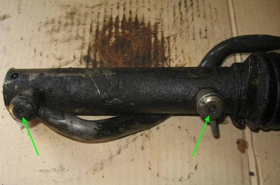
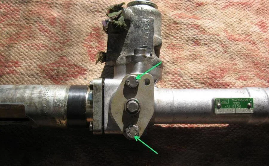
Using a 6mm Allen key, unscrew the pipe securing bolts. The heads of these bolts are often rounded off (as was the case here), so you may have to use a cold chisel or a pipe wrench.
Once the pipes are removed, unscrew the clamps and remove the gaiter. Clean the rack thoroughly if you haven't done so already. Plug the pipe holes with clean cloth beforehand.
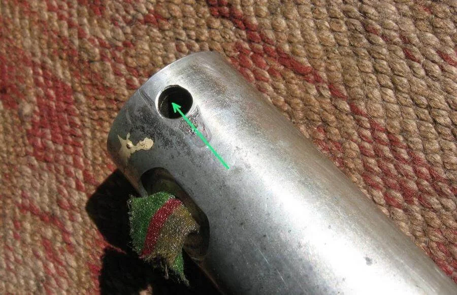
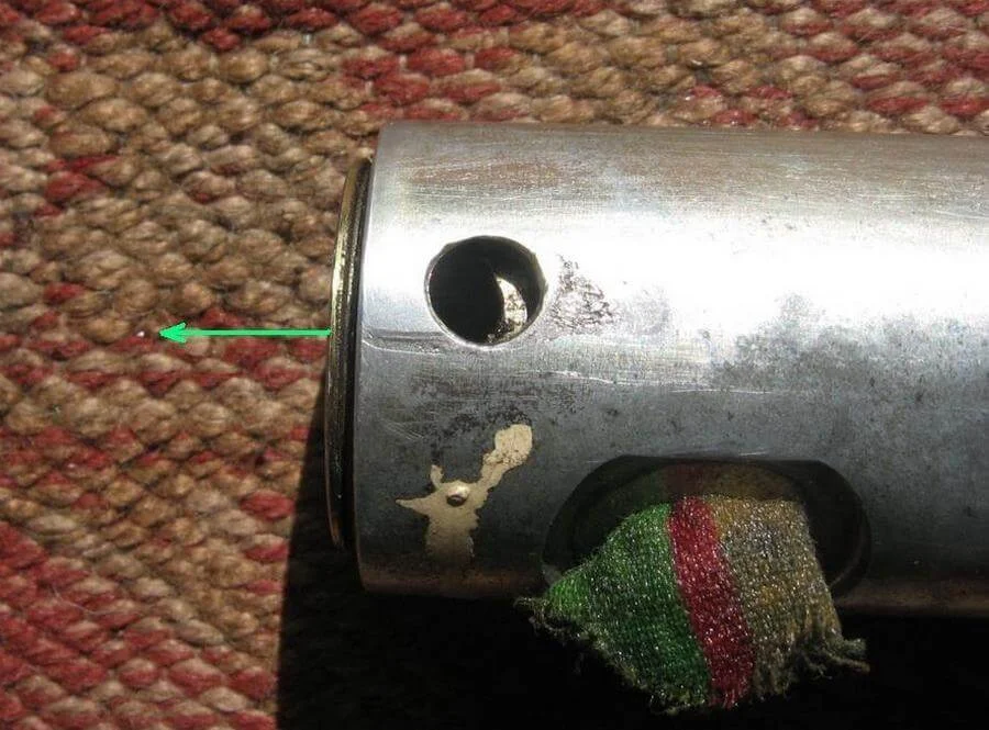
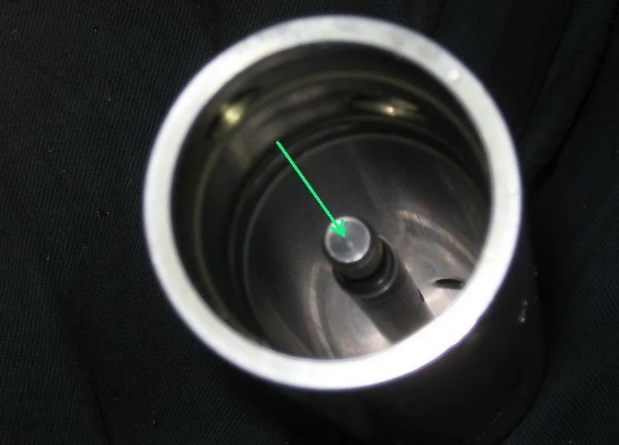
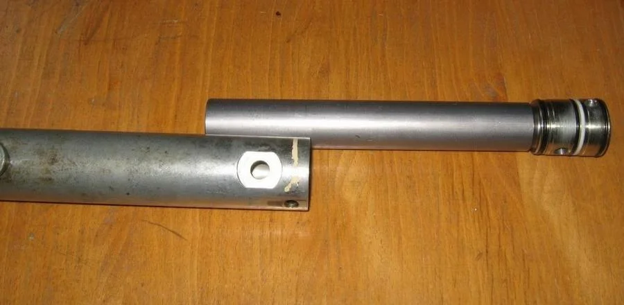
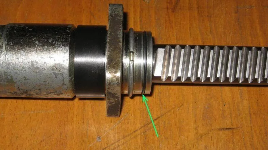
Through the hole in the end of the rack (used for mounting to the body), gently tap the inner cylinder out of the housing using a punch or screwdriver, then pull it out.
Unscrew the nut securing the piston to the rod.
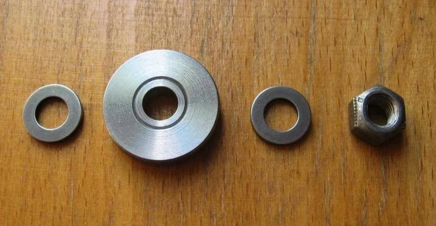
Remove the piston. Note that washers are fitted on both sides.
Unscrew the bolts on the thrust mechanism cover.
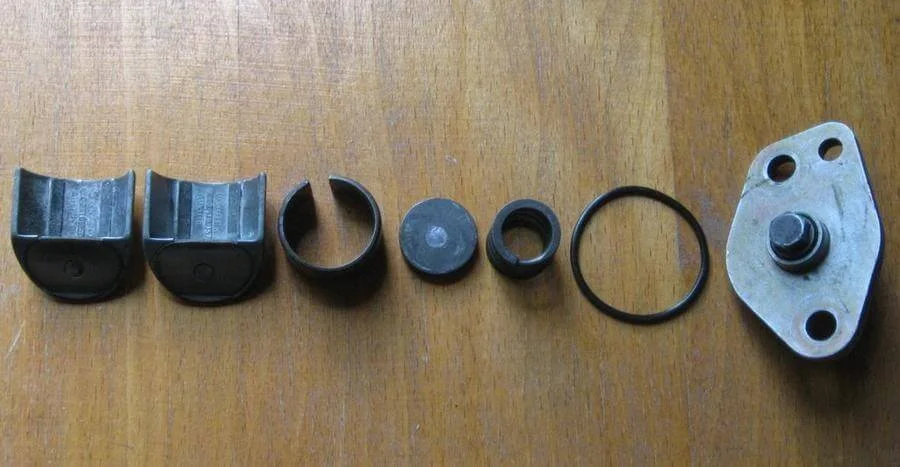
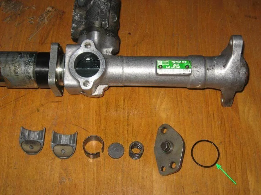
Remove the spring, thrust washer, pressure ring, and guides.
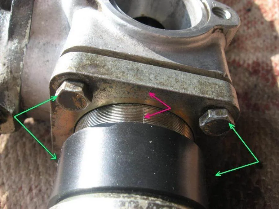
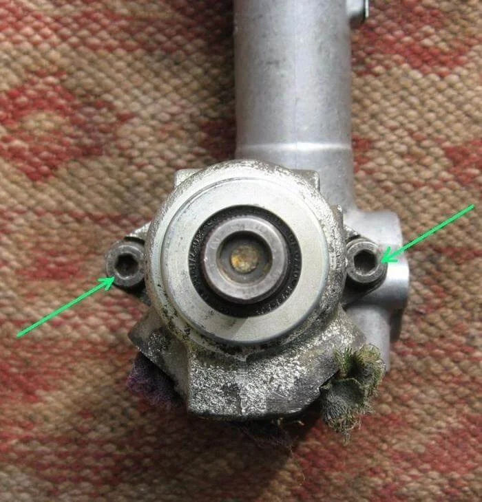
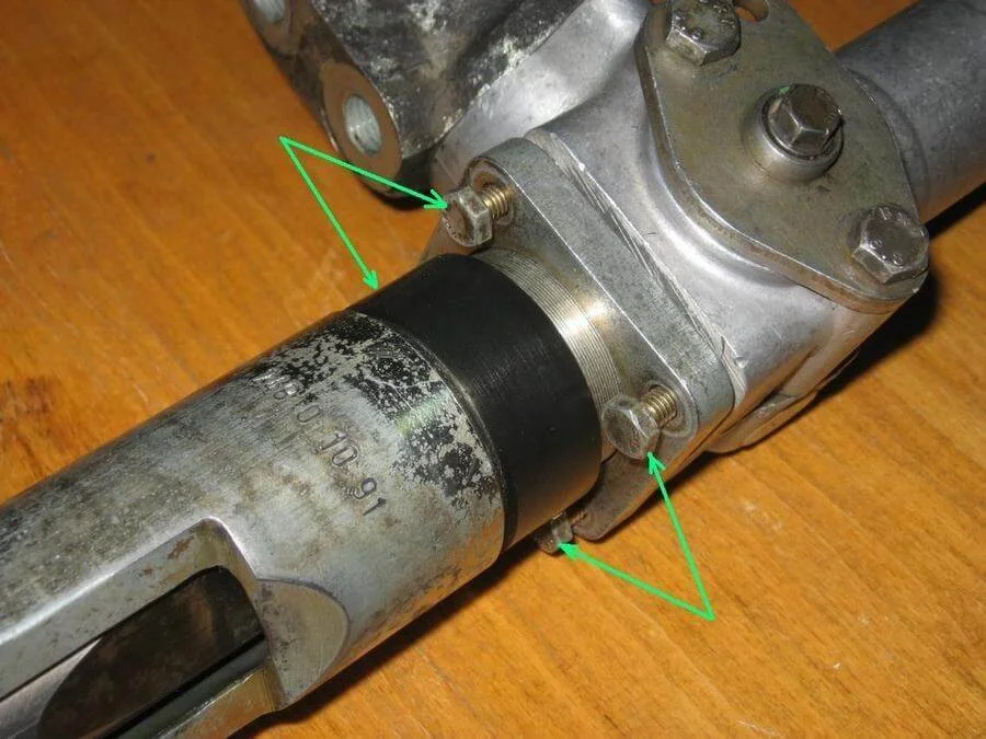
Mark the position of the two housing halves relative to each other with a sharp tool (red arrows). Unscrew the four bolts joining the halves.
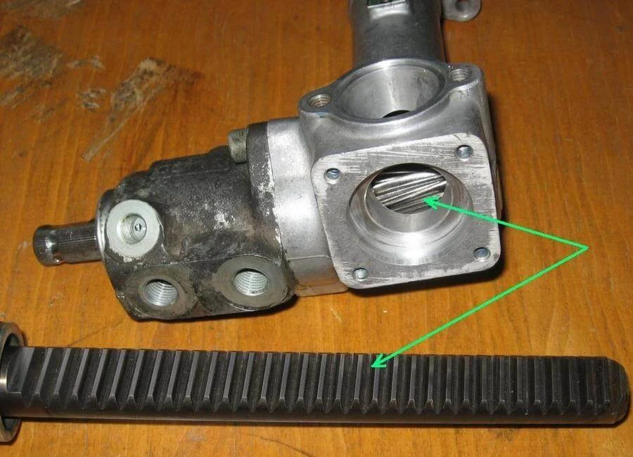
Separate the housing halves and remove the rack rod.
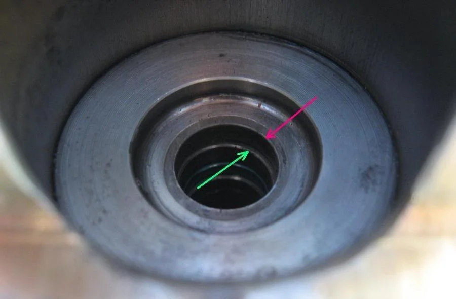
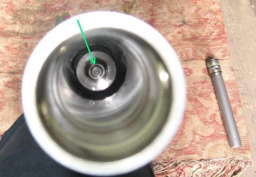
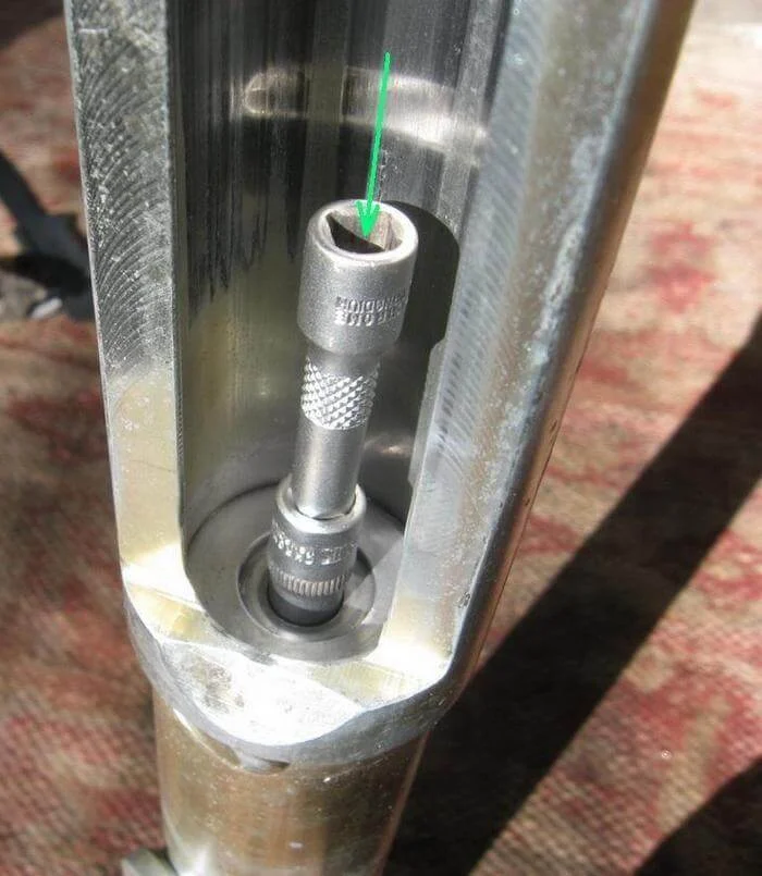
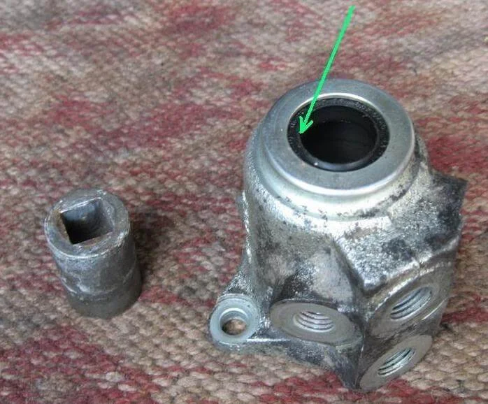
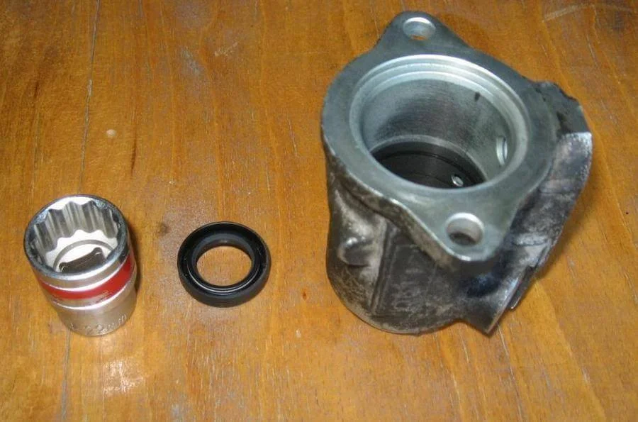
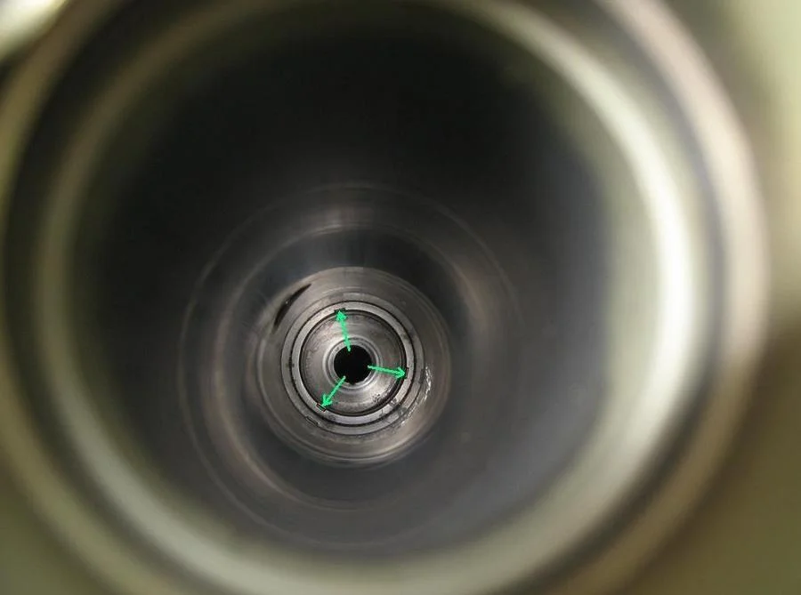
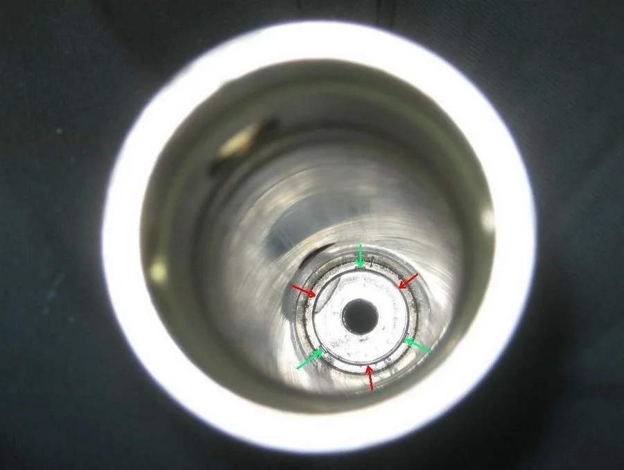
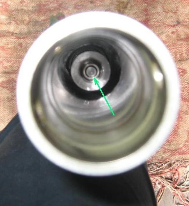
A sleeve with the seal assembly is pressed into the housing; it must be knocked out. To do this, select a drift that fits through the hole (red arrow) but rests against the seal (green arrow). A socket from a toolkit worked well for this diameter.
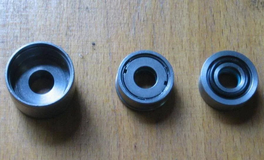
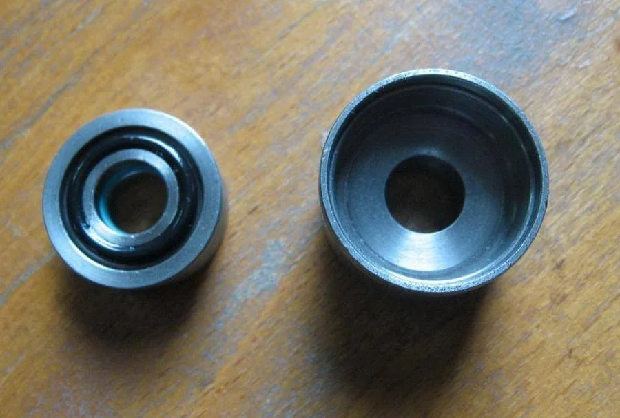
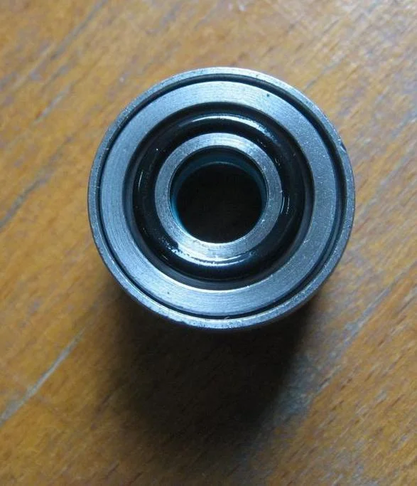
Seal assembly: sleeve, old oil seal, new oil seal.
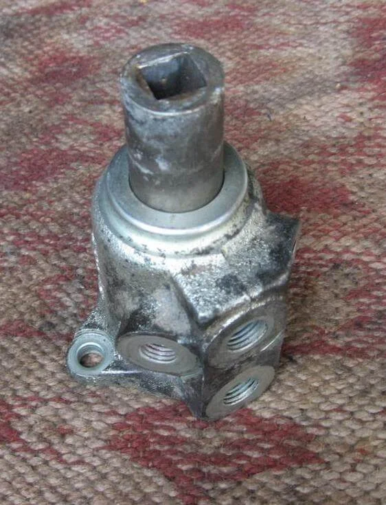
Unscrew the two bolts on the pinion valve housing.
Remove the housing, not forgetting the washer.
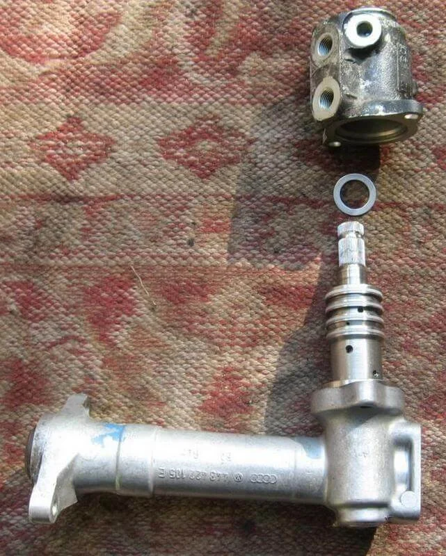
Remove the pinion valve assembly.
Remove the seal (it is lightly pressed in) and the O-ring.
Using a suitable mandrel, press the seal out of the housing.
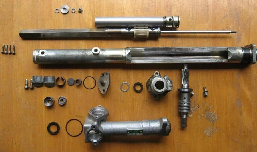
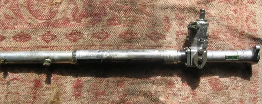
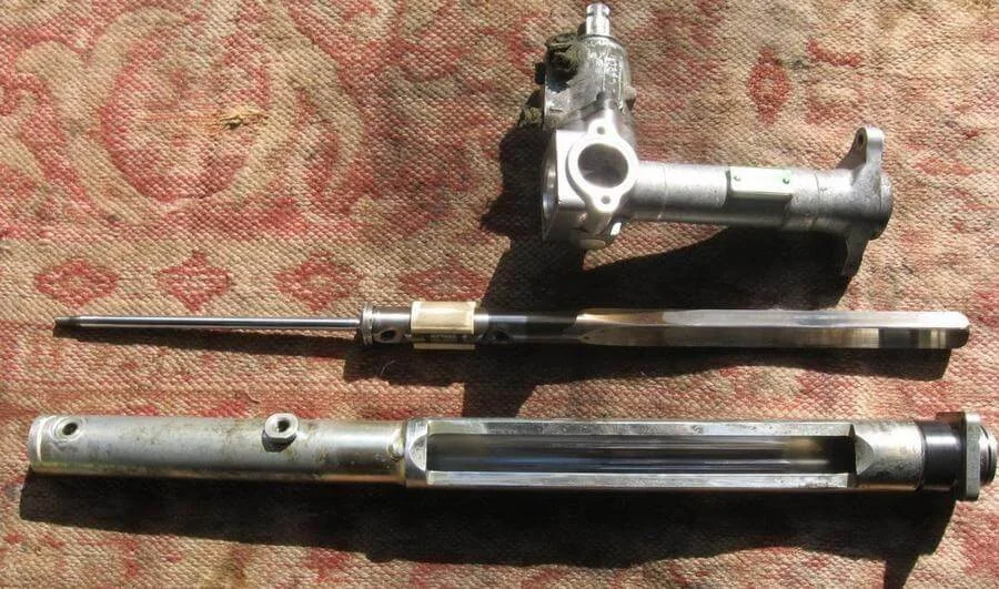
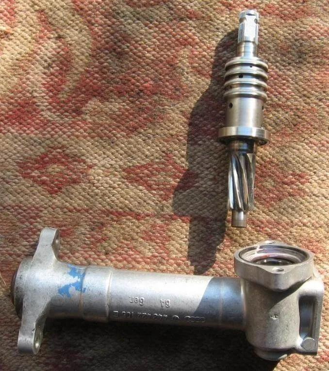
The rack in a completely disassembled state.
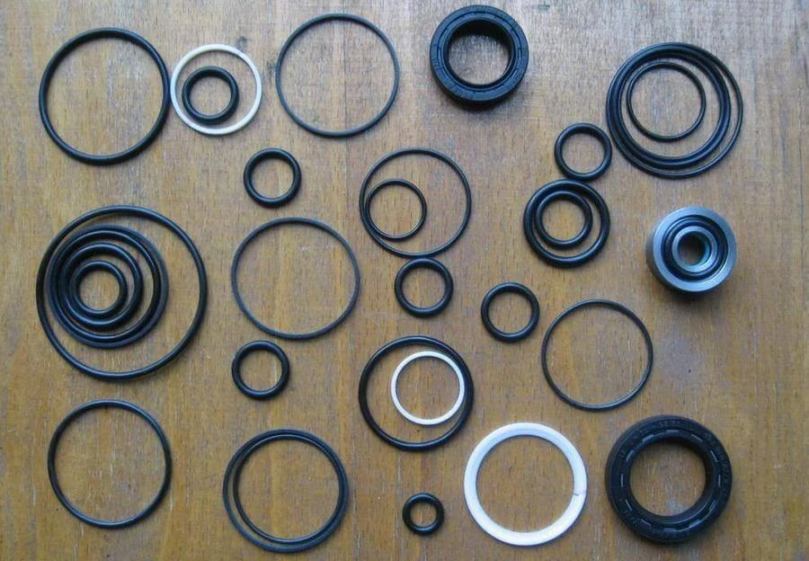
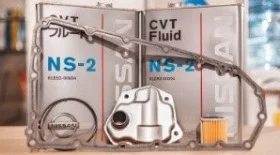
Contents of the repair kit.
Press the new seal from the kit into the pinion housing using a suitable mandrel.
Install the new seal into the rack housing by hand and replace the O-ring with a new one.
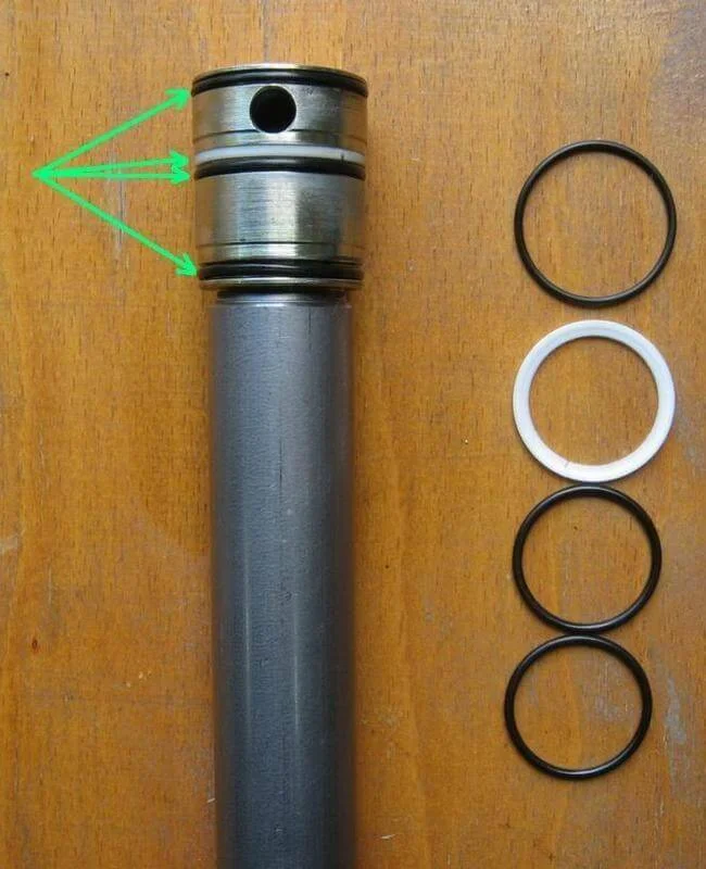
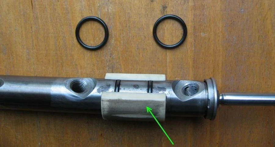
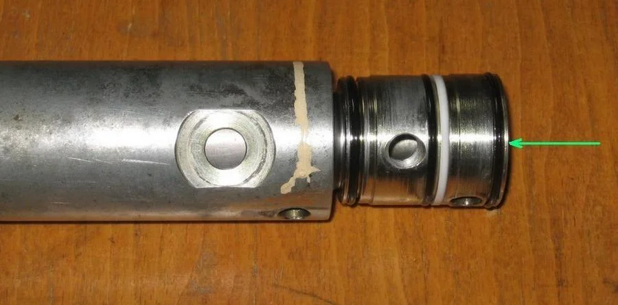
Replace the three rubber rings and one plastic ring on the rack cylinder.
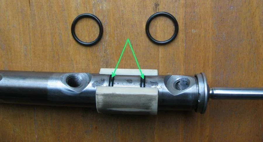
Replace the two O-rings on the rack rod under the bush. If the rack bush shows heavy wear, this may be the cause of knocking. In this case, the bush needs to be replaced (ZF catalogue number 7847035106).
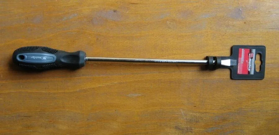
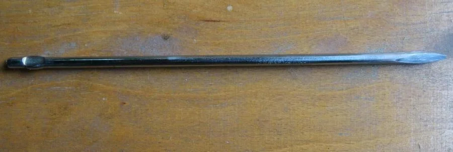
To press the seal assembly into the rack housing, you will need a long drift. You can make one from a long screwdriver by cutting off the handle and sharpening the tip. When grinding, try not to overheat the tip to avoid softening the metal.
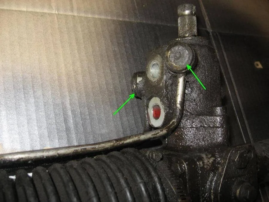
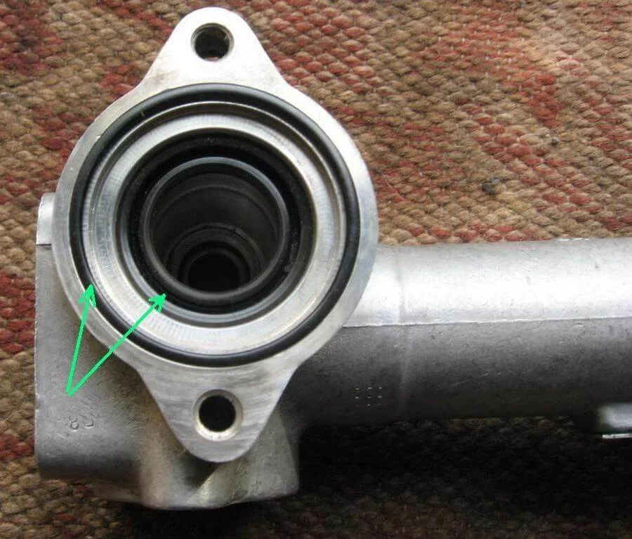
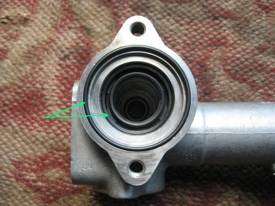
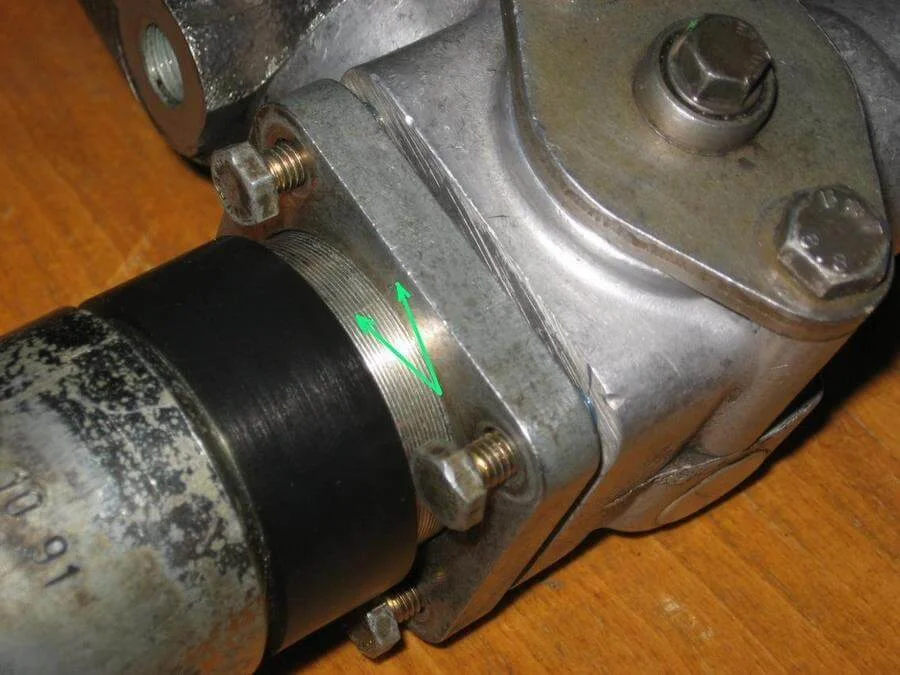
Here are the points in the rack housing where factory peening (staking) is applied.
Take the new seal from the kit and insert it into the sleeve.
To guide the seal assembly to its seating position, insert the rack rod into the housing. Slide the seal assembly onto the rod, lubricating it liberally with PAS fluid (do this carefully so as not to damage the seal lip). Use a piece of pipe to press the seal assembly into the rack housing.
Remove the rod. Using your custom tool, peen the housing at the three factory points (green arrows). For reliability, you can peen it at three additional points (red arrows).
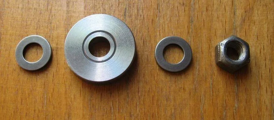
Insert the rack rod into the housing (don't forget to lubricate everything liberally), and fit the piston with washers. Tighten the nut using threadlocker.
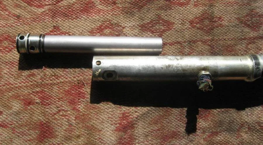
Insert the cylinder into the rack housing.
Replace the O-ring on the rack housing.
Apply grease to the rack teeth and the worm gear. It is recommended to use the original AOF06300004 grease or specialised equivalents for steering racks. The use of standard multi-purpose greases is highly discouraged, as they are not designed for these loads.
Assemble the thrust mechanism. Replace the O-ring from the kit. If the rack was knocking, the guides (on the left in the photo, No. 30 in the diagram) need replacing — the plastic washers on them wear out. VAG number 443419148. Use the same specialised grease during assembly.
Align the marks made earlier on the housing. Tighten the bolts joining the rack halves using threadlocker.
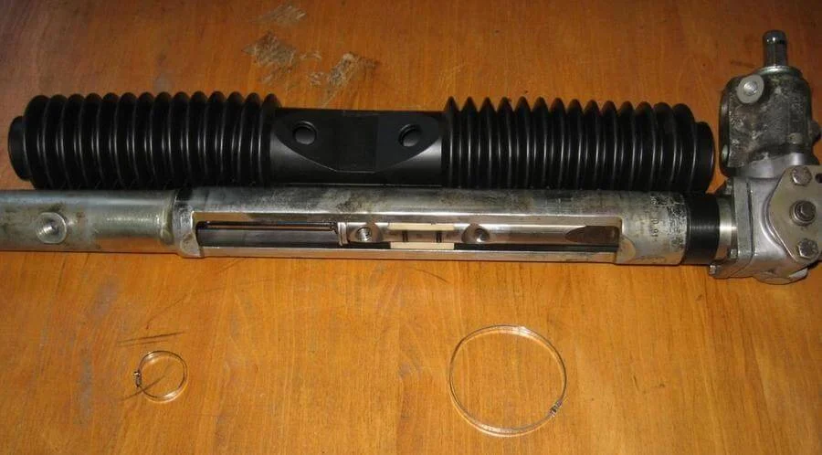
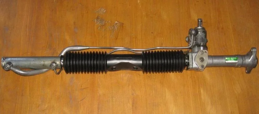
Take the new gaiter with clamps (pictured is Lemforder 3012001, which comes with two clamps). VAG boot number is 43141983.
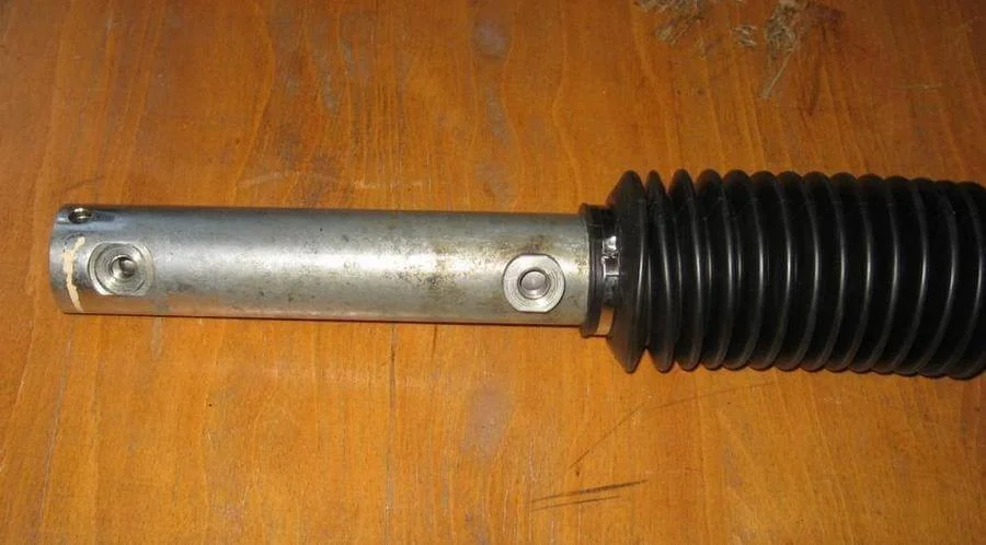
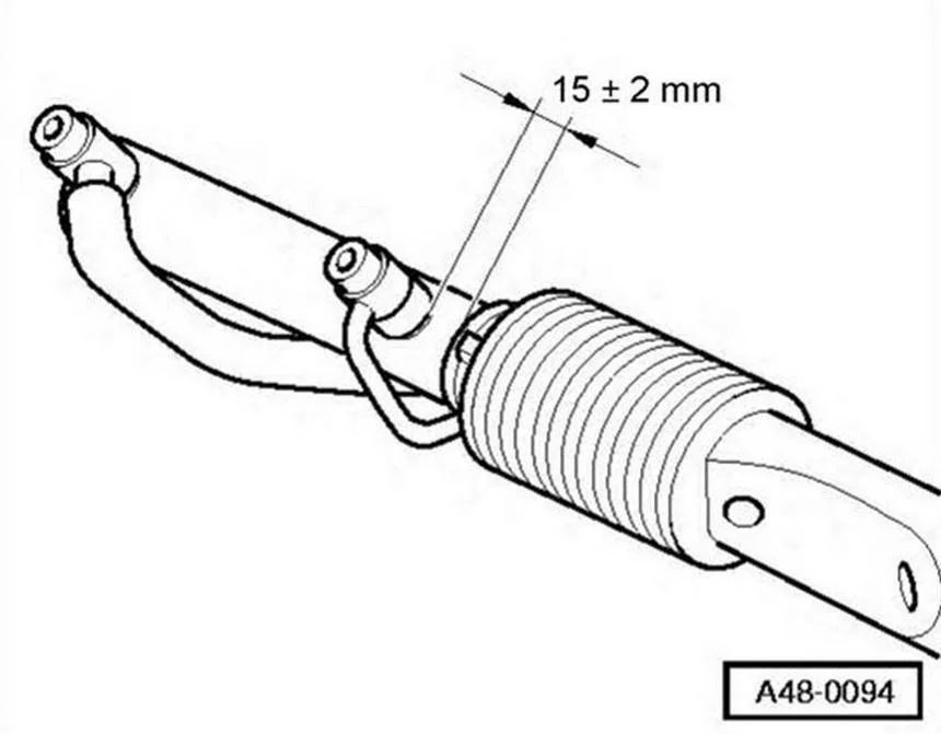
Slide the gaiter onto the rack, set the necessary distance from the gaiter to the bush, and secure the clamps.
Bolt the pipes to the rack, replacing the sealing rings with new ones from the kit.
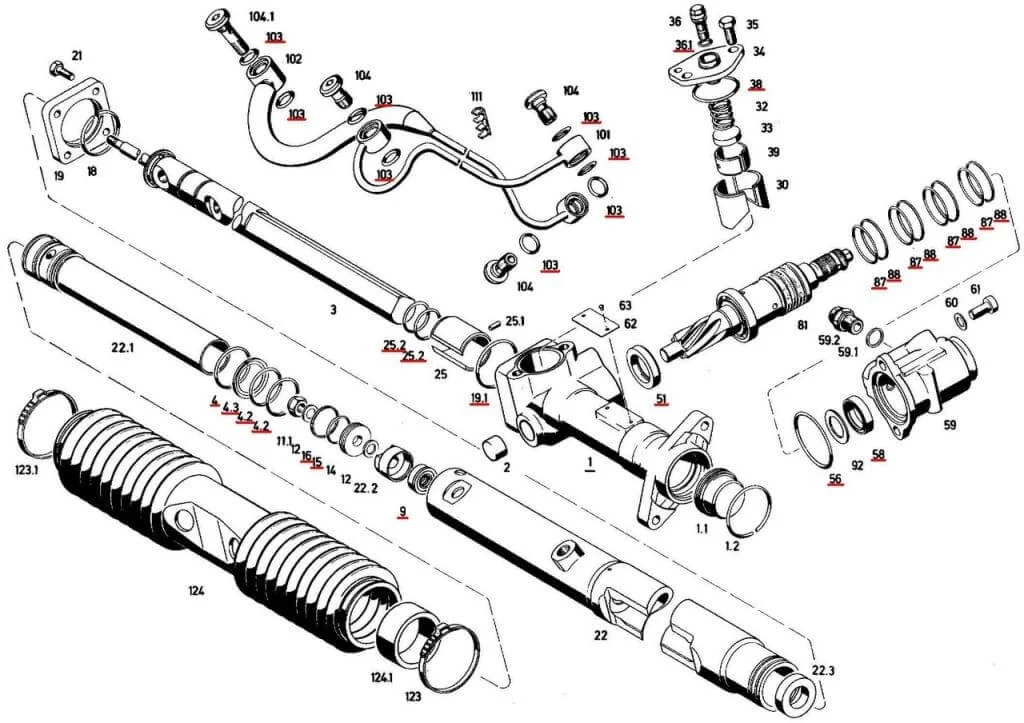
Rack diagram from the ZF catalogue. Red underlines indicate parts included in the ZF 7847633009 repair kit. The original VAG repair kit is 4A1498020 (for versions with Servotronic — 4A1498020A).
Important: During this rebuild, the Teflon rings on the pinion and piston (numbers 15, 16, 87, 88) were not changed, as they are plastic and require special mandrels (cones) for stretching and subsequent compression. If you do not have these special tools, it is extremely difficult to replace them without damage.
Was this guide useful?
Your feedback helps us improve our content.
Related Materials

Discussion (0)
No comments yet!