Timing Belt Replacement on Lexus RX300 (1MZ-FE Engine)
In this photo guide, we are carrying out a timing belt replacement on a Lexus RX300 equipped with the 1MZ-FE engine. This procedure is also applicable to other Lexus and Toyota models featuring this motor. Replacing the timing belt and all associated components is not a simple task; it requires experience, knowledge, and a comprehensive set of tools:
- Socket set (1/2, 1/4 drive);
- Ratchets, at least two — 1/4 (small) and 1/2 with a long handle;
- Various extensions and, ideally, a universal joint;
- Torque wrench;
- 10 mm hex key (Allen key);
- Set of ring spanners;
- Pliers, long-nose pliers, side cutters;
- Long flathead screwdriver;
- Cross-head screwdriver (Phillips);
- Small hammer;
- Stud extractor;
In addition to the tools listed above, you should also prepare the following materials and supplies:
- WD-40;
- Lithium-based grease;
- Medium strength thread locker;
- Nylon cable ties;
- Self-tapping screws (for extracting oil seals);
- Small inspection mirror;
- Torch;
- Coolant (matching the type currently in the system);
- Impact wrench and impact sockets (desirable);
- If fabricating pullers yourself — welder, drill, angle grinder;
Source: diyservice.blogspot.com
Which timing belt and tensioners to fit on the 1MZ-FE?
Original timing belt part number: 13568-20020 (or manufacturer substitution 13568-29025).
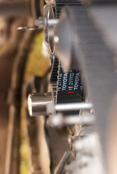
Quality aftermarket alternatives:
- Contitech CT1029
- SUN A664Y32MM
- LYNXauto 211AL32
- Mitsuboshi 211 S8M 32
Guide (idler) pulley number — 13503-62030.
Tensioner pulley — 13505-20010.
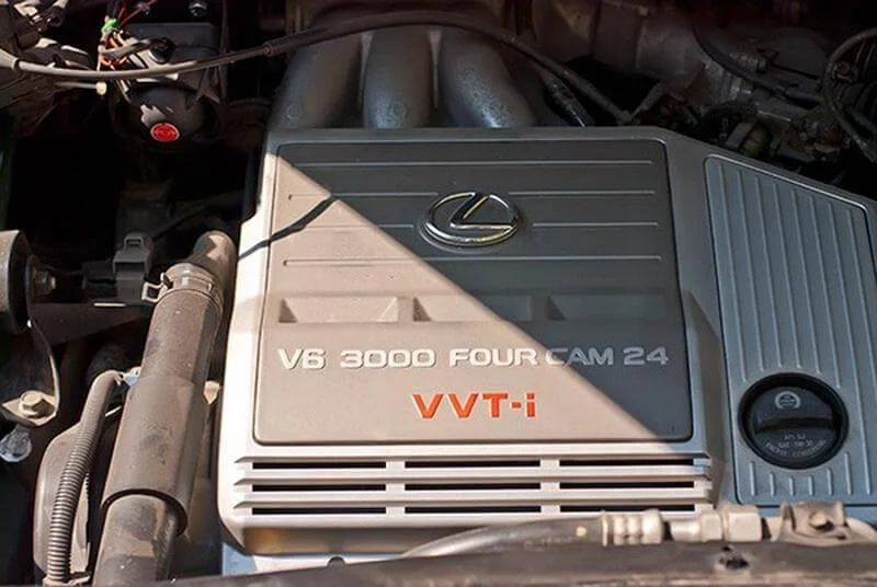
Our 'patient' is a 3.0-litre, 24-valve 1MZ-FE engine in a Lexus RX300.
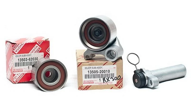
When servicing the valve timing mechanism, in addition to the belt itself, it is mandatory to replace the two rollers — the tensioner pulley and the idler pulley. This engine model also uses an automatic hydraulic belt tensioner, which is worth replacing as a precaution (especially on high-mileage vehicles).
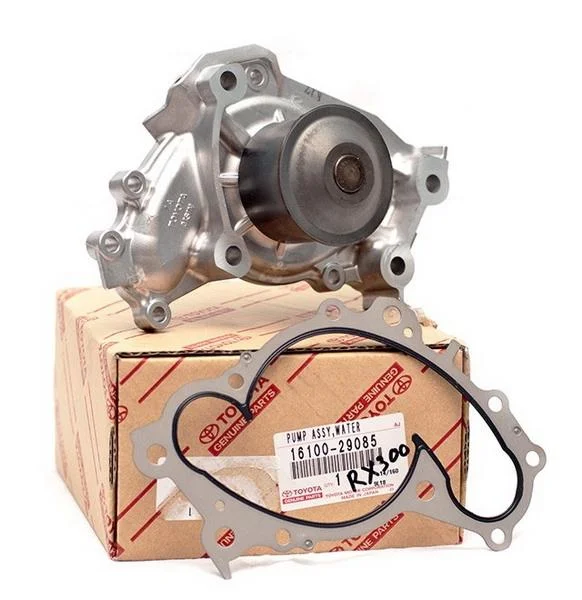
The water pump should also be replaced: on this engine, it is driven by the smooth (back) side of the timing belt. Despite the pump having a longer service life than the rollers, the risk of the old pump seizing or leaking is significant. To avoid stripping everything down again in 10-20 thousand km, the pump should be replaced; ensure you buy a new one complete with a gasket.
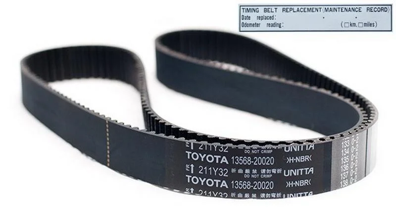
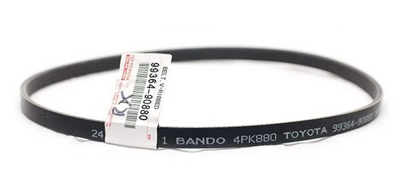
Timing belt. The kit often includes a sticker on which you must record the date and mileage at the time of replacement. To perform the full procedure, you will also need to acquire oil seals: the front crankshaft seal (oil pump seal) and two camshaft seals.
At your discretion, you can also replace the auxiliary drive belts — power steering (PAS) and alternator/air conditioning, as they will have to be removed anyway.

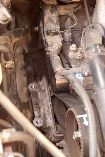
We begin the procedure by protecting the wing from accidental damage. It is recommended to cover it with a suitably sized piece of cloth or a wing cover.
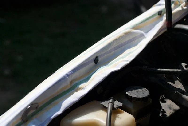
The cloth can be secured, for example, with a few sufficiently strong magnets.
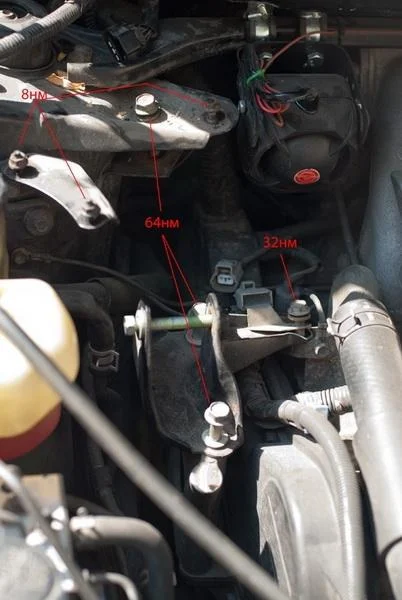
Disconnect the two earth wire connectors, unscrew the cruise control actuator mount, move it to the right, and unscrew the bracket. Remove the upper engine mount (torque strut/dog bone) and the engine suspension bracket.
Next, loosen the locking bolt on the alternator belt tensioning mechanism, and also loosen the alternator mounting bolt. Unscrew the tensioner bolt until the belt can be removed. Jack up the car, remove the front right wheel and the protective plastic splash shield (held by two bolts) — this gives us access to the crankshaft pulley.
Tip: To avoid losing the removed bolts, carefully place them in labelled containers or thread them back into their original holes.
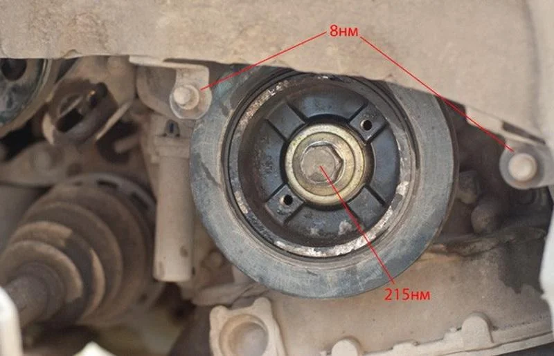
Loosen the PAS (power steering) pump tensioner bolt, as well as the mounting bolt, push the pump upwards, and remove the belt. The next procedure is one of the most difficult in this process — undoing the crankshaft pulley bolt.
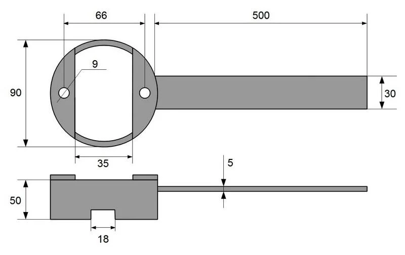
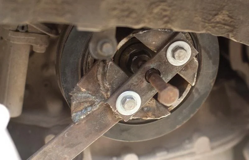
The pulley bolt is usually tightened very securely (plus thread locker). Even an impact wrench with up to 800 Nm of torque (if available) is unlikely to help. Options like using the starter motor or locking the flywheel are risky. Ideally, use a special holding tool for the crankshaft pulley. If unavailable, you can fabricate an analogue yourself.
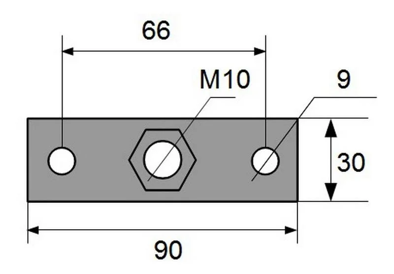
To make the puller/holder you need: a section of pipe with an outer diameter of 90 mm and length of 50 mm, a strip of steel 30x5 mm about 700 mm long, and two M8x60 bolts.
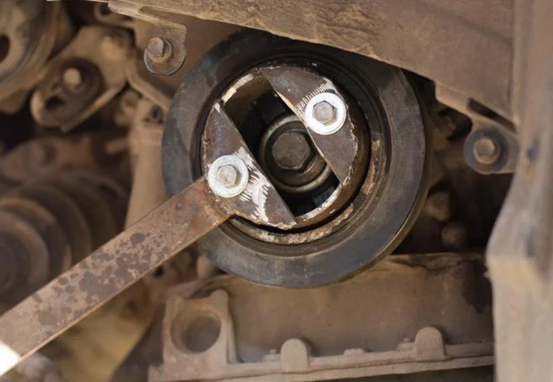
The fabricated tool is fixed to the pulley with two M8 bolts, the long lever is braced against the ground (via a block) or the chassis rail, after which the pulley bolt is unscrewed with considerable force.
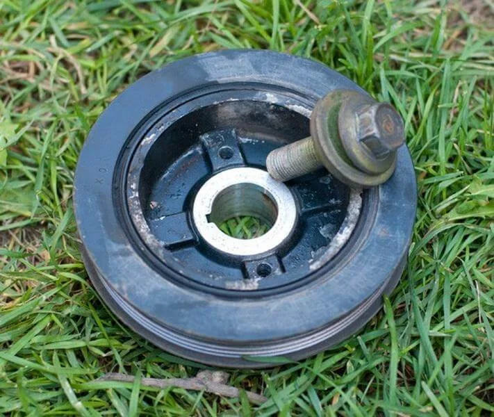
Once the bolt is removed, the pulley itself needs to be taken off. It is unlikely you can do this by hand.
Screw the pulley bolt back into the crankshaft (not fully); it will serve as a pivot point. Secure the puller to the pulley and gradually screw the central M10 bolt into the puller. Pushing against the crankshaft bolt, it will draw the pulley off.
You can ignore the welded reinforcements shown — in our case, the bolt was tightened too much, so the tool had to be reinforced on the spot.
After long and persistent work, the pulley is removed.
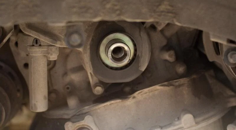
Unscrew the 4 bolts, remove the lower plastic timing belt cover and the belt guide washer from the shaft. Do not lose the crankshaft woodruff key!
Remove the wiring channel from the brackets, unscrew the 5 bolts, remove the upper timing belt cover, and then the alternator bracket.
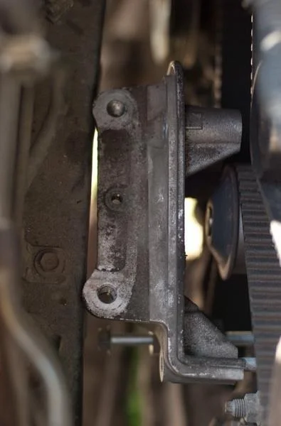
The engine mount rests against the body and is held by two bolts and a nut, which must be removed.
To remove the mount, which is slotted onto studs in the block, you need to raise the engine slightly with a jack by a few centimetres. Be sure to use a wide wooden block and a rubber mat between the jack and the sump to avoid denting the oil pan.
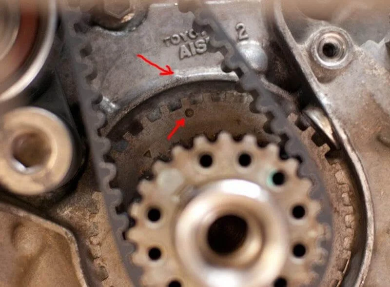
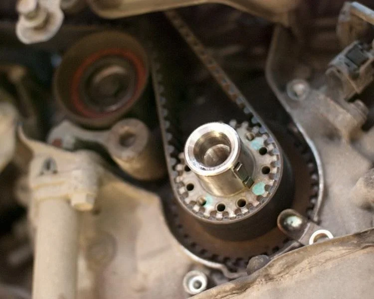
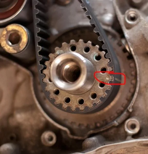
Turning the crankshaft clockwise (with the bolt screwed back in), set the first cylinder to Top Dead Centre (TDC). To do this, align the mark on the crankshaft sprocket with the mark on the oil pump housing. At the same time, check that the marks on the camshaft pulleys align with the marks on the inner cover. If the camshaft marks are 'looking' in different directions or downwards, rotate the crankshaft one more full turn. (See photos of marks below).
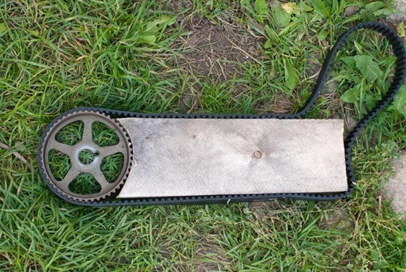
Remove the old belt. Remove the belt tensioner and measure the rod protrusion (standard: 10–10.8 mm). If reusing the old tensioner, it must be reset by compressing the rod. This requires a force of at least 100 kg (use a vice). Important: the tensioner must be in the 'rod up' position during compression. Slowly push the rod in until the holes in the rod and body align, then lock it by inserting a suitable hex key or drill bit (a 'pin'). Then remove the camshaft pulleys (to replace the seals). To hold the pulleys from rotating, you can use the old timing belt screwed to a wooden board with a cut-out arc.
Since wood is a soft material, damage to the tooth surface is prevented. Unscrew the 6 bolts and remove the inner metal timing belt cover (shield).
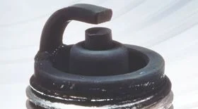
Drain the coolant from the radiator and block (if accessible). To remove the water pump, you need to unscrew the upper stud (requires a stud extractor or the 'double nut' method). Unscrew the pump mounting bolts and one nut, then remove the pump. Be careful: residual coolant will gush out. Remove the old gasket and clean the surface.
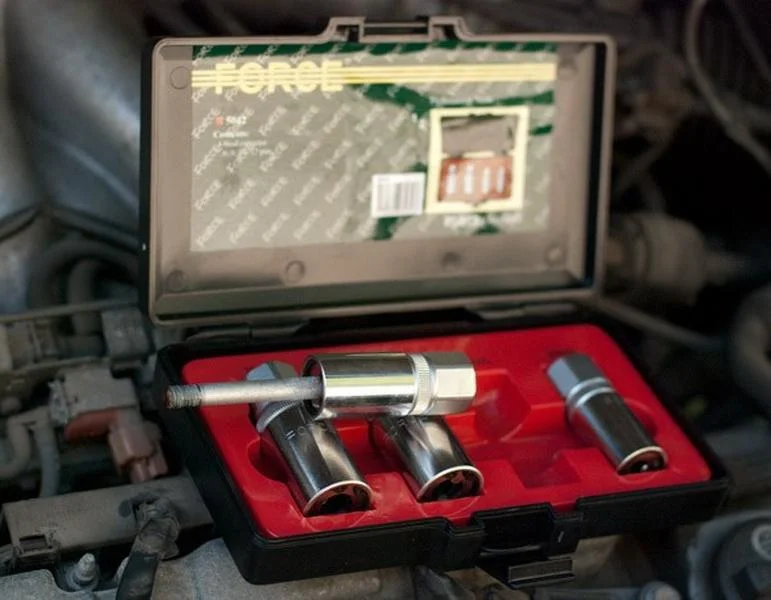
This is what a stud extractor looks like.
Wipe and degrease the pump mating surface on the block. Install a new gasket and secure the new pump. Screw the extracted stud back into place.
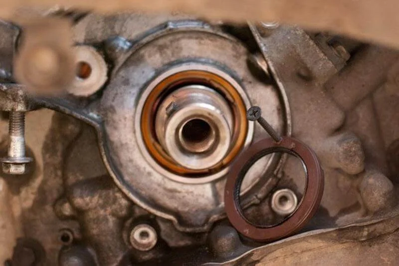
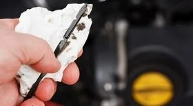
Move on to changing the seals (crankshaft and camshafts). It is important to remember the depth at which the old seal was seated. The easiest way to remove the old seal is with a hardened self-tapping screw. Screw the screw a couple of turns into the body of the seal (between the shaft and the housing, carefully, without scratching the shaft!). Then use pliers to pull the seal out by the screw. Wipe the seating area and the shaft. Grease the working lip and outer edge of the new seal with lithium grease. The new seal is pressed in using a mandrel or a suitable socket.
Begin reassembly. Reinstall:
1. The inner metal cover (6 bolts, torque 8.5 Nm).
2. The crankshaft sprocket.
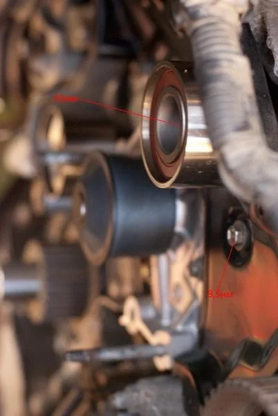
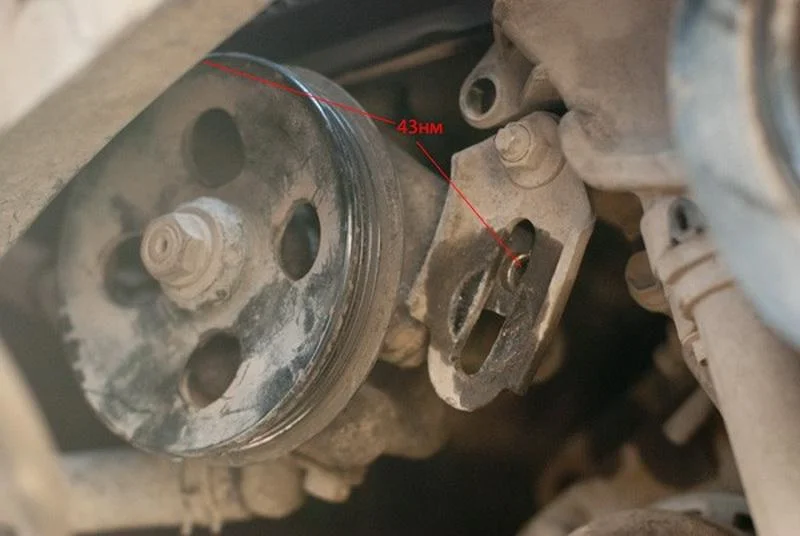
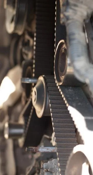
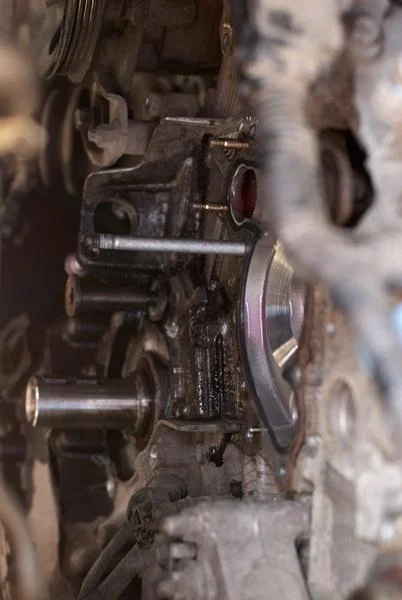
Install the new idler pulley (tightening torque 45 Nm).
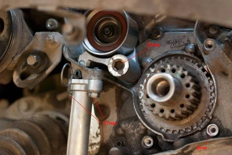
Note on photo: the tensioner is shown for illustration, do not fit it before installing the belt! It is impossible to fit a new, unstretched belt with the tensioner installed.
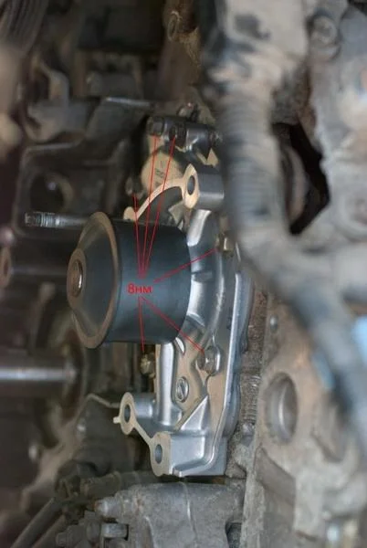
Install the tensioner pulley (having applied thread locker to the bolt beforehand), torque to 34 Nm. Ensure the rollers spin freely and the tensioner pulley bracket moves without binding.
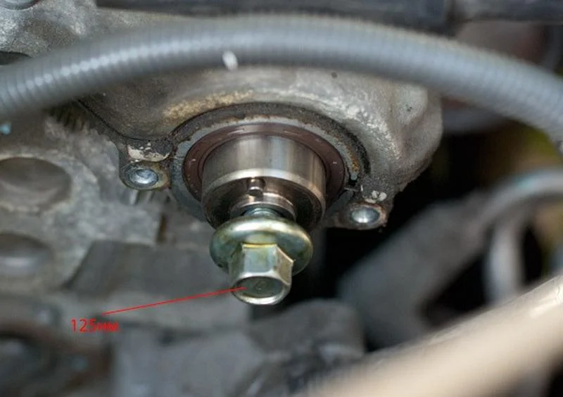
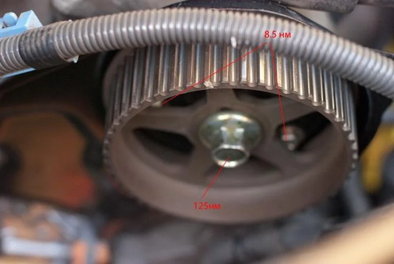
Install the camshaft pulleys (torque 125 Nm). Note: the pulley for the rear (left) camshaft is installed with the flange guide facing outwards, and the front (right) one with the flange facing inwards.
Begin fitting the new timing belt. If there are marks on the belt, follow them strictly:
- The 'FR' (front) mark or arrows must point 'away from the engine' (in the direction of belt travel).
- Align the dotted mark on the belt with the mark on the crankshaft sprocket.
- Route the belt behind the water pump pulley.
- Loop the belt around the front camshaft pulley, aligning the mark on the belt with the mark on the sprocket. Secure the belt on the pulley with a cable tie or binder clip (to prevent it jumping teeth).
- Route the belt around the idler pulley.
- Loop it over the rear camshaft pulley (again aligning marks and securing with a tie).
- Fit the belt onto the tensioner pulley (this will be tight).
Only now install the hydraulic belt tensioner (27 Nm), but do not remove the locking pin yet. Thoroughly check the alignment of all marks, using a mirror for the rear shaft.
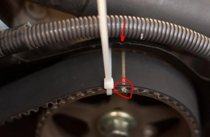
Mark on the front camshaft sprocket (must align with the mark on the cover and the line on the belt).
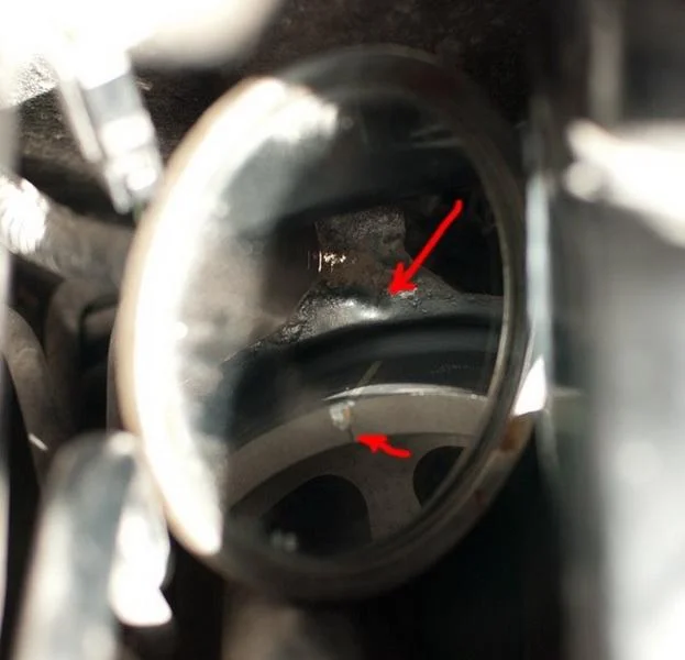
Mark on the rear camshaft sprocket (view through a mirror).
If everything matches, pull the pin out of the tensioner. Wait a moment for the rod to extend and tension the belt. Rotate the crankshaft clockwise two full turns and check the timing marks again. If everything aligns, reassemble all removed parts in reverse order.
Was this guide useful?
Your feedback helps us improve our content.


Discussion (0)
No comments yet!